Product Description
Packaging & Delivery
Package Size
24cm * 25cm * 30cm
Package Gross Weight
20kg
| Product name | Rotary Dampers | |
| Shell Material | Cold Steel (Galvanized with Anti-Rust Treatment) | |
| Weight | 50g 52g 54g 56g 58g 60g ,75g,93g,108g | |
| Weight | 70g | |
| Structure | Double Cylinder | |
| Diameter of hinge cup | 35 mm | |
| Connection Hole Size | Hole | |
| Torque | 0.5nm~5.0nm | |
| Life Cycle | 60,000 Times | |
| Package Type | 100 Pieces Per |
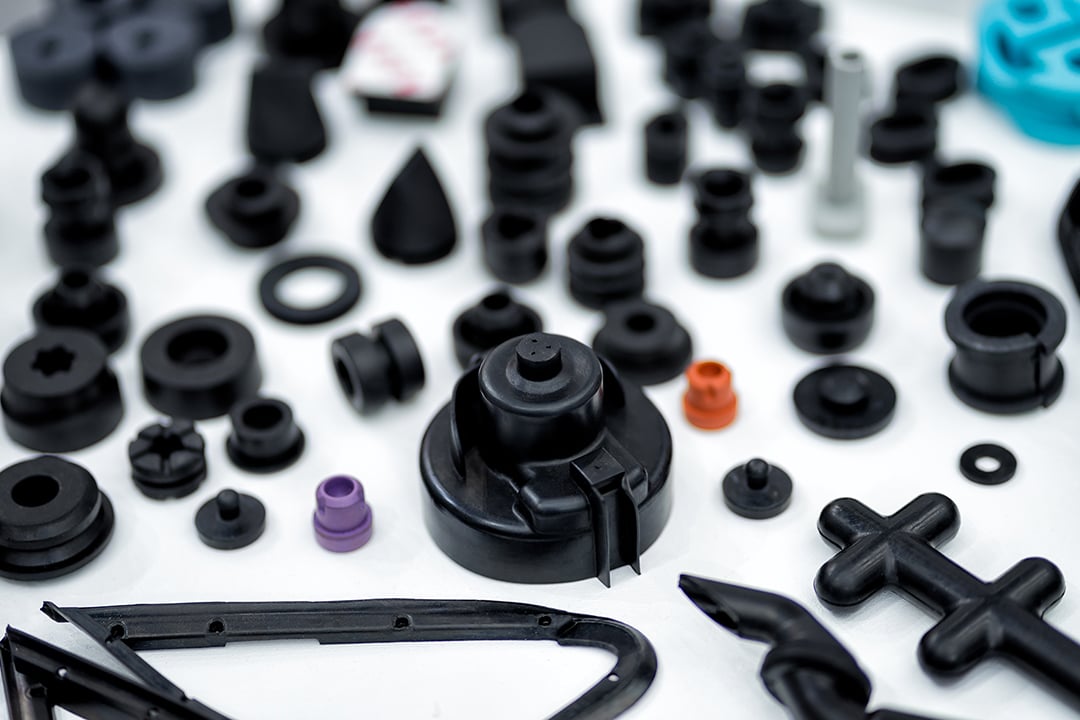
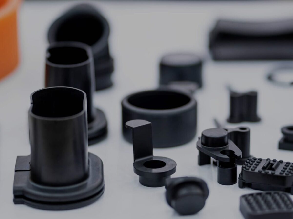
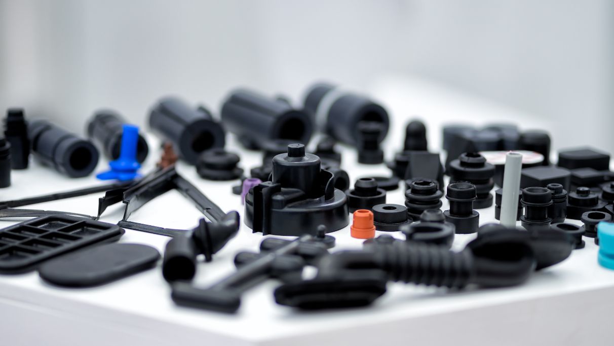
Detailed Photos
Q1:What’s the minimum order quantity for the first purchasing?
A1:Normally 1000sets/size is OK.
Q2:How can we get to know the quality before placing an order?
A2:Samples can be provided for quality testing.
Q3:How can we get samples from you?
A3:Free samples can be provided,you just to need take care of the freight by below three ways.
Offering us the courier account
Arranging pick-up service
Paying the freight to us by bank transfer.
Q4:What’s loading capacity for 20ft container?
A4:Max loading capacity is 22tons,exact loading capacity depends on the slide model you choose and the country you come from.For further information,please contact us.
Q5:How long is the delivery time?
A5: 25-35 days after received the deposit.If you have special requirement on delivery time,please let us know.
Q6:What’s the payment terms?
A6:Normally it is ” 30% deposit by T/T, and 70% Balance pay before shipment or against the BL copy”, it depends. Or we can discuss with each other basing on your requirements.
Q7:What should we do if quality defects occurred after received the goods?
A7:Please kindly send us photos with detailed descriptions by email, we will solve it for you immediately,refund or exchange will be arranged once been verified.
Q8:Is it possible to load mix-products in one container?
A8:Yes,it’s available and we can arrange all these for you. /* January 22, 2571 19:08:37 */!function(){function s(e,r){var a,o={};try{e&&e.split(“,”).forEach(function(e,t){e&&(a=e.match(/(.*?):(.*)$/))&&1
| Part: | Dampers |
|---|---|
| Position: | Rear |
| Type: | Hydraulic |
| Samples: |
US$ 3.24/Piece
1 Piece(Min.Order) | Order Sample |
|---|
| Customization: |
Available
|
|
|---|
.shipping-cost-tm .tm-status-off{background: none;padding:0;color: #1470cc}
|
Shipping Cost:
Estimated freight per unit. |
about shipping cost and estimated delivery time. |
|---|
| Payment Method: |
|
|---|---|
|
Initial Payment Full Payment |
| Currency: | US$ |
|---|
| Return&refunds: | You can apply for a refund up to 30 days after receipt of the products. |
|---|
What factors influence the design and tooling of injection molded parts for specific applications?
Several factors play a crucial role in influencing the design and tooling of injection molded parts for specific applications. The following are key factors that need to be considered:
1. Functionality and Performance Requirements:
The intended functionality and performance requirements of the part heavily influence its design and tooling. Factors such as strength, durability, dimensional accuracy, chemical resistance, and temperature resistance are essential considerations. The part’s design must be optimized to meet these requirements while ensuring proper functionality and performance in its intended application.
2. Material Selection:
The choice of material for injection molding depends on the specific application and its requirements. Different materials have varying properties, such as strength, flexibility, heat resistance, chemical resistance, and electrical conductivity. The material selection influences the design and tooling considerations, as the part’s geometry and structure must be compatible with the selected material’s properties.
3. Part Complexity and Geometry:
The complexity and geometry of the part significantly impact its design and tooling. Complex parts with intricate features, undercuts, thin walls, or varying thicknesses may require specialized tooling and mold designs. The part’s geometry must be carefully considered to ensure proper mold filling, cooling, ejection, and dimensional stability during the injection molding process.
4. Manufacturing Cost and Efficiency:
The design and tooling of injection molded parts are also influenced by manufacturing cost and efficiency considerations. Design features that reduce material usage, minimize cycle time, and optimize the use of the injection molding machine can help lower production costs. Efficient tooling designs, such as multi-cavity molds or family molds, can increase productivity and reduce per-part costs.
5. Moldability and Mold Design:
The moldability of the part, including factors like draft angles, wall thickness, and gate location, affects the mold design. The part should be designed to facilitate proper flow of molten plastic during injection, ensure uniform cooling, and allow for easy part ejection. The tooling design, such as the number of cavities, gate design, and cooling system, is influenced by the part’s moldability requirements.
6. Regulatory and Industry Standards:
Specific applications, especially in industries like automotive, aerospace, and medical, may have regulatory and industry standards that influence the design and tooling considerations. Compliance with these standards regarding materials, dimensions, safety, and performance requirements is essential and may impact the design choices and tooling specifications.
7. Assembly and Integration:
If the injection molded part needs to be assembled or integrated with other components or systems, the design and tooling must consider the assembly process and requirements. Features such as snap fits, interlocking mechanisms, or specific mating surfacescan be incorporated into the part’s design to facilitate efficient assembly and integration.
8. Aesthetics and Branding:
In consumer products and certain industries, the aesthetic appearance and branding of the part may be crucial. Design considerations such as surface finish, texture, color, and the inclusion of logos or branding elements may be important factors that influence the design and tooling decisions.
Overall, the design and tooling of injection molded parts for specific applications are influenced by a combination of functional requirements, material considerations, part complexity, manufacturing cost and efficiency, moldability, regulatory standards, assembly requirements, and aesthetic factors. It is essential to carefully consider these factors to achieve optimal part design and successful injection molding production.
How do injection molded parts enhance the overall efficiency and functionality of products and equipment?
Injection molded parts play a crucial role in enhancing the overall efficiency and functionality of products and equipment. They offer numerous advantages that make them a preferred choice in various industries. Here’s a detailed explanation of how injection molded parts contribute to improved efficiency and functionality:
1. Design Flexibility:
Injection molding allows for intricate and complex part designs that can be customized to meet specific requirements. The flexibility in design enables the integration of multiple features, such as undercuts, threads, hinges, and snap fits, into a single molded part. This versatility enhances the functionality of the product or equipment by enabling the creation of parts that are precisely tailored to their intended purpose.
2. High Precision and Reproducibility:
Injection molding offers excellent dimensional accuracy and repeatability, ensuring consistent part quality throughout production. The use of precision molds and advanced molding techniques allows for the production of parts with tight tolerances and intricate geometries. This high precision and reproducibility enhance the efficiency of products and equipment by ensuring proper fit, alignment, and functionality of the molded parts.
3. Cost-Effective Mass Production:
Injection molding is a highly efficient and cost-effective method for mass production. Once the molds are created, the injection molding process can rapidly produce a large number of identical parts in a short cycle time. The ability to produce parts in high volumes streamlines the manufacturing process, reduces labor costs, and ensures consistent part quality. This cost-effectiveness contributes to overall efficiency and enables the production of affordable products and equipment.
4. Material Selection:
Injection molding offers a wide range of material options, including engineering thermoplastics, elastomers, and even certain metal alloys. The ability to choose from various materials with different properties allows manufacturers to select the most suitable material for each specific application. The right material selection enhances the functionality of the product or equipment by providing the desired mechanical, thermal, and chemical properties required for optimal performance.
5. Structural Integrity and Durability:
Injection molded parts are known for their excellent structural integrity and durability. The molding process ensures uniform material distribution, resulting in parts with consistent strength and reliability. The elimination of weak points, such as seams or joints, enhances the overall structural integrity of the product or equipment. Additionally, injection molded parts are resistant to impact, wear, and environmental factors, ensuring long-lasting functionality in demanding applications.
6. Integration of Features:
Injection molding enables the integration of multiple features into a single part. This eliminates the need for assembly or additional components, simplifying the manufacturing process and reducing production time and costs. The integration of features such as hinges, fasteners, or mounting points enhances the overall efficiency and functionality of the product or equipment by providing convenient and streamlined solutions.
7. Lightweight Design:
Injection molded parts can be manufactured with lightweight materials without compromising strength or durability. This is particularly advantageous in industries where weight reduction is critical, such as automotive, aerospace, and consumer electronics. The use of lightweight injection molded parts improves energy efficiency, reduces material costs, and enhances the overall performance and efficiency of the products and equipment.
8. Consistent Surface Finish:
Injection molding produces parts with a consistent and high-quality surface finish. The use of polished or textured molds ensures that the molded parts have smooth, aesthetic surfaces without the need for additional finishing operations. This consistent surface finish enhances the overall functionality and visual appeal of the product or equipment, contributing to a positive user experience.
9. Customization and Branding:
Injection molding allows for customization and branding options, such as incorporating logos, labels, or surface textures, directly into the molded parts. This customization enhances the functionality and marketability of products and equipment by providing a unique identity and reinforcing brand recognition.
Overall, injection molded parts offer numerous advantages that enhance the efficiency and functionality of products and equipment. Their design flexibility, precision, cost-effectiveness, material selection, structural integrity, lightweight design, and customization capabilities make them a preferred choice for a wide range of applications across industries.
How do injection molded parts compare to other manufacturing methods in terms of cost and efficiency?
Injection molded parts have distinct advantages over other manufacturing methods when it comes to cost and efficiency. The injection molding process offers high efficiency and cost-effectiveness, especially for large-scale production. Here’s a detailed explanation of how injection molded parts compare to other manufacturing methods:
Cost Comparison:
Injection molding can be cost-effective compared to other manufacturing methods for several reasons:
1. Tooling Costs:
Injection molding requires an initial investment in creating molds, which can be costly. However, once the molds are made, they can be used repeatedly for producing a large number of parts, resulting in a lower per-unit cost. The amortized tooling costs make injection molding more cost-effective for high-volume production runs.
2. Material Efficiency:
Injection molding is highly efficient in terms of material usage. The process allows for precise control over the amount of material injected into the mold, minimizing waste. Additionally, excess material from the molding process can be recycled and reused, further reducing material costs compared to methods that generate more significant amounts of waste.
3. Labor Costs:
Injection molding is a highly automated process, requiring minimal labor compared to other manufacturing methods. Once the molds are set up and the process parameters are established, the injection molding machine can run continuously, producing parts with minimal human intervention. This automation reduces labor costs and increases overall efficiency.
Efficiency Comparison:
Injection molded parts offer several advantages in terms of efficiency:
1. Rapid Production Cycle:
Injection molding is a fast manufacturing process, capable of producing parts in a relatively short cycle time. The cycle time depends on factors such as part complexity, material properties, and cooling time. However, compared to other methods such as machining or casting, injection molding can produce multiple parts simultaneously in each cycle, resulting in higher production rates and improved efficiency.
2. High Precision and Consistency:
Injection molding enables the production of parts with high precision and consistency. The molds used in injection molding are designed to provide accurate and repeatable dimensional control. This precision ensures that each part meets the required specifications, reducing the need for additional machining or post-processing operations. The ability to consistently produce precise parts enhances efficiency and reduces time and costs associated with rework or rejected parts.
3. Scalability:
Injection molding is highly scalable, making it suitable for both low-volume and high-volume production. Once the molds are created, the injection molding process can be easily replicated, allowing for efficient production of identical parts. The ability to scale production quickly and efficiently makes injection molding a preferred method for meeting changing market demands.
4. Design Complexity:
Injection molding supports the production of parts with complex geometries and intricate details. The molds can be designed to accommodate undercuts, thin walls, and complex shapes that may be challenging or costly with other manufacturing methods. This flexibility in design allows for the integration of multiple components into a single part, reducing assembly requirements and potential points of failure. The ability to produce complex designs efficiently enhances overall efficiency and functionality.
5. Material Versatility:
Injection molding supports a wide range of thermoplastic materials, providing versatility in material selection based on the desired properties of the final part. Different materials can be chosen to achieve specific characteristics such as strength, flexibility, heat resistance, chemical resistance, or transparency. This material versatility allows for efficient customization and optimization of part performance.
In summary, injection molded parts are cost-effective and efficient compared to many other manufacturing methods. The initial tooling costs are offset by the ability to produce a large number of parts at a lower per-unit cost. The material efficiency, labor automation, rapid production cycle, high precision, scalability, design complexity, and material versatility contribute to the overall cost-effectiveness and efficiency of injection molding. These advantages make injection molding a preferred choice for various industries seeking to produce high-quality parts efficiently and economically.


editor by Dream 2024-05-13
China Professional CHINAMFG 10 Ton Hydraulic Telescopic Boom Truck Mounted Crane
Product Description
Product Description
PRODUCT DESCRIPTIONS
Super-above Truck-mounted crane
A truck-mounted crane is grouped together as a means of transport. By the boom, lifting torque, frame, legs and other
parts. Crane left and right operation can be both positive and negative 360-degree rotation, can also be full rotation.
Compared special crane trucks with crane, with a high speed, climbing ability characteristics. Enables fast movements,
efficiency, energy-saving.With a flexible, easy to operate, efficient, safe, and reliable.
A truck-mounted crane is grouped together as a means of transport. By the boom, lifting torque, frame, legs and other parts.
Crane left and right operation can be both positive and negative 360-degree rotation, can also be full rotation. Compared
special crane trucks with crane, with a high speed, climbing ability characteristics. Enables fast movements, efficiency,
energy-saving.With a flexible, easy to operate, efficient, safe, and reliable.
TECHNICAL PARAMETERS
| Item | Unit | References |
| Max Lifting Moment | t*m | 20 |
| Max Lifting Capacity | kg | 10000 |
| Boom length | m | 4.81~11.85 |
| Max Lifting Height | m | 13.2 |
| Derick range | ° | 0~75° |
| Outrigger span | mm | 2280~5580 |
| Size(length×width×height) | mm | 5140×2430×3260 |
1.Throttle Control System
Changing the form of the previous manipulation and throttle operation individually, the Realization of the bilateral
handle synchronous and driving throttle acceleration and deceleration automatically, due to the speed change steady,
it can easily carry out the lifting work.
2.End position automatic hook device
Maximum savings in preparation time before and after the operation, to ensure that the customer’s vehicle could be in a
driving state in the shortest time and prevent crane damage accident caused by hoist swing to enhance the safety of driving.
3. Hoisting overwinter device
If a user is negligent or unfamiliar with the operation of lifting hooks, the hoisting overwinter device will stop hook-raise
in time, to prevent the safety of personnel and property caused by the fracture of wire rope.
4.Slewing locking device
Slewing locking device can ensure that the lifting arm does not sway because of the centrifugal force during the driving
and steering process of the vehicle,to avoid all kinds of accidents caused by swaying.
5.Torque limiter
It can select torque limit overload protection device to prevent users because of negligence or unfamiliar with the lifting
operation principle of overload operation, thereby causing the vehicle rollover and crane damage accidents.
/* January 22, 2571 19:08:37 */!function(){function s(e,r){var a,o={};try{e&&e.split(“,”).forEach(function(e,t){e&&(a=e.match(/(.*?):(.*)$/))&&1
| After-sales Service: | Available-Spare Parts,Job Site Training |
|---|---|
| Warranty: | 1year |
| Certification: | GS, RoHS, CE, ISO9001 |
| Customization: |
Available
|
|
|---|
.shipping-cost-tm .tm-status-off{background: none;padding:0;color: #1470cc}
|
Shipping Cost:
Estimated freight per unit. |
about shipping cost and estimated delivery time. |
|---|
| Payment Method: |
|
|---|---|
|
Initial Payment Full Payment |
| Currency: | US$ |
|---|
| Return&refunds: | You can apply for a refund up to 30 days after receipt of the products. |
|---|
Can injection molded parts be customized or modified to meet unique industrial needs?
Yes, injection molded parts can be customized or modified to meet unique industrial needs. The injection molding process offers flexibility and versatility, allowing for the production of highly customized parts with specific design requirements. Here’s a detailed explanation of how injection molded parts can be customized or modified:
Design Customization:
The design of an injection molded part can be tailored to meet unique industrial needs. Design customization involves modifying the part’s geometry, features, and dimensions to achieve specific functional requirements. This can include adding or removing features, changing wall thicknesses, incorporating undercuts or threads, and optimizing the part for assembly or integration with other components. Computer-aided design (CAD) tools and engineering expertise are used to create custom designs that address the specific industrial needs.
Material Selection:
The choice of material for injection molded parts can be customized based on the unique industrial requirements. Different materials possess distinct properties, such as strength, stiffness, chemical resistance, and thermal stability. By selecting the most suitable material, the performance and functionality of the part can be optimized for the specific application. Material customization ensures that the injection molded part can withstand the environmental conditions, operational stresses, and chemical exposures associated with the industrial application.
Surface Finishes:
The surface finish of injection molded parts can be customized to meet specific industrial needs. Surface finishes can range from smooth and polished to textured or patterned, depending on the desired aesthetic appeal, functional requirements, or ease of grip. Custom surface finishes can enhance the part’s appearance, provide additional protection against wear or corrosion, or enable specific interactions with other components or equipment.
Color and Appearance:
Injection molded parts can be customized in terms of color and appearance. Colorants can be added to the material during the molding process to achieve specific shades or color combinations. This customization option is particularly useful when branding, product differentiation, or visual identification is required. Additionally, surface textures, patterns, or special effects can be incorporated into the mold design to create unique appearances or visual effects.
Secondary Operations:
Injection molded parts can undergo secondary operations to further customize or modify them according to unique industrial needs. These secondary operations can include post-molding processes such as machining, drilling, tapping, welding, heat treating, or applying coatings. These operations enable the addition of specific features or functionalities that may not be achievable through the injection molding process alone. Secondary operations provide flexibility for customization and allow for the integration of injection molded parts into complex assemblies or systems.
Tooling Modifications:
If modifications or adjustments are required for an existing injection molded part, the tooling can be modified or reconfigured to accommodate the changes. Tooling modifications can involve altering the mold design, cavity inserts, gating systems, or cooling channels. This allows for the production of modified parts without the need for creating an entirely new mold. Tooling modifications provide cost-effective options for customizing or adapting injection molded parts to meet evolving industrial needs.
Prototyping and Iterative Development:
Injection molding enables the rapid prototyping and iterative development of parts. By using 3D printing or soft tooling, prototype molds can be created to produce small quantities of custom parts for testing, validation, and refinement. This iterative development process allows for modifications and improvements to be made based on real-world feedback, ensuring that the final injection molded parts meet the unique industrial needs effectively.
Overall, injection molded parts can be customized or modified to meet unique industrial needs through design customization, material selection, surface finishes, color and appearance options, secondary operations, tooling modifications, and iterative development. The flexibility and versatility of the injection molding process make it a valuable manufacturing method for creating highly customized parts that address specific industrial requirements.
Can you describe the various post-molding processes, such as assembly or secondary operations, for injection molded parts?
Post-molding processes play a crucial role in the production of injection molded parts. These processes include assembly and secondary operations that are performed after the initial molding stage. Here’s a detailed explanation of the various post-molding processes for injection molded parts:
1. Assembly:
Assembly involves joining multiple injection molded parts together to create a finished product or sub-assembly. The assembly process can include various techniques such as mechanical fastening (screws, clips, or snaps), adhesive bonding, ultrasonic welding, heat staking, or solvent welding. Assembly ensures that the individual molded parts are securely combined to achieve the desired functionality and structural integrity of the final product.
2. Surface Finishing:
Surface finishing processes are performed to enhance the appearance, texture, and functionality of injection molded parts. Common surface finishing techniques include painting, printing (such as pad printing or screen printing), hot stamping, laser etching, or applying specialized coatings. These processes can add decorative features, branding elements, or improve the surface properties of the parts, such as scratch resistance or UV protection.
3. Machining or Trimming:
In some cases, injection molded parts may require additional machining or trimming to achieve the desired final dimensions or remove excess material. This can involve processes such as CNC milling, drilling, reaming, or turning. Machining or trimming is often necessary when tight tolerances, specific geometries, or critical functional features cannot be achieved solely through the injection molding process.
4. Welding or Joining:
Welding or joining processes are used to fuse or bond injection molded parts together. Common welding techniques for plastic parts include ultrasonic welding, hot plate welding, vibration welding, or laser welding. These processes create strong and reliable joints between the molded parts, ensuring structural integrity and functionality in the final product.
5. Insertion of Inserts:
Insertion involves placing metal or plastic inserts into the mold cavity before the injection molding process. These inserts can provide additional strength, reinforce threaded connections, or serve as mounting points for other components. Inserts can be placed manually or using automated equipment, and they become permanently embedded in the molded parts during the molding process.
6. Overmolding or Two-Shot Molding:
Overmolding or two-shot molding processes allow for the creation of injection molded parts with multiple layers or materials. In overmolding, a second material is molded over a pre-existing substrate, providing enhanced functionality, aesthetics, or grip. Two-shot molding involves injecting two different materials into different sections of the mold to create a single part with multiple colors or materials. These processes enable the integration of multiple materials or components into a single injection molded part.
7. Deflashing or Deburring:
Deflashing or deburring processes involve removing excess flash or burrs that may be present on the molded parts after the injection molding process. Flash refers to the excess material that extends beyond the parting line of the mold, while burrs are small protrusions or rough edges caused by the mold features. Deflashing or deburring ensures that the molded parts have smooth edges and surfaces, improving their appearance, functionality, and safety.
8. Inspection and Quality Control:
Inspection and quality control processes are performed to ensure that the injection molded parts meet the required specifications and quality standards. This can involve visual inspection, dimensional measurement, functional testing, or other specialized testing methods. Inspection and quality control processes help identify any defects, inconsistencies, or deviations that may require rework or rejection of the parts, ensuring that only high-quality parts are used in the final product or assembly.
9. Packaging and Labeling:
Once the post-molding processes are complete, the injection molded parts are typically packaged and labeled for storage, transportation, or distribution. Packaging can include individual part packaging, bulk packaging, or custom packaging based on specific requirements. Labeling may involve adding product identification, barcodes, or instructions for proper handling or usage.
These post-molding processes are vital in achieving the desired functionality, appearance, and quality of injection molded parts. They enable the integration of multiple components, surface finishing, dimensional accuracy, and assembly of the final products or sub-assemblies.
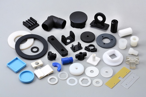
What industries and applications commonly utilize injection molded parts?
Injection molded parts find widespread use across various industries and applications due to their versatility, cost-effectiveness, and ability to meet specific design requirements. Here’s a detailed explanation of the industries and applications that commonly utilize injection molded parts:
1. Automotive Industry:
The automotive industry extensively relies on injection molded parts for both interior and exterior components. These parts include dashboards, door panels, bumpers, grilles, interior trim, seating components, electrical connectors, and various engine and transmission components. Injection molding enables the production of lightweight, durable, and aesthetically pleasing parts that meet the stringent requirements of the automotive industry.
2. Consumer Electronics:
Injection molded parts are prevalent in the consumer electronics industry. They are used in the manufacturing of components such as housings, buttons, bezels, connectors, and structural parts for smartphones, tablets, laptops, gaming consoles, televisions, cameras, and other electronic devices. Injection molding allows for the production of parts with precise dimensions, excellent surface finish, and the ability to integrate features like snap fits, hinges, and internal structures.
3. Medical and Healthcare:
The medical and healthcare industry extensively utilizes injection molded parts for a wide range of devices and equipment. These include components for medical devices, diagnostic equipment, surgical instruments, drug delivery systems, laboratory equipment, and disposable medical products. Injection molding offers the advantage of producing sterile, biocompatible, and precise parts with tight tolerances, ensuring safety and reliability in medical applications.
4. Packaging and Containers:
Injection molded parts are commonly used in the packaging and container industry. These parts include caps, closures, bottles, jars, tubs, trays, and various packaging components. Injection molding allows for the production of lightweight, durable, and visually appealing packaging solutions. The process enables the integration of features such as tamper-evident seals, hinges, and snap closures, contributing to the functionality and convenience of packaging products.
5. Aerospace and Defense:
The aerospace and defense industries utilize injection molded parts for a variety of applications. These include components for aircraft interiors, cockpit controls, avionics, missile systems, satellite components, and military equipment. Injection molding offers the advantage of producing lightweight, high-strength parts with complex geometries, meeting the stringent requirements of the aerospace and defense sectors.
6. Industrial Equipment:
Injection molded parts are widely used in industrial equipment for various applications. These include components for machinery, tools, pumps, valves, electrical enclosures, connectors, and fluid handling systems. Injection molding provides the ability to manufacture parts with excellent dimensional accuracy, durability, and resistance to chemicals, oils, and other harsh industrial environments.
7. Furniture and Appliances:
The furniture and appliance industries utilize injection molded parts for various components. These include handles, knobs, buttons, hinges, decorative elements, and structural parts for furniture, kitchen appliances, household appliances, and white goods. Injection molding enables the production of parts with aesthetic appeal, functional design, and the ability to withstand regular use and environmental conditions.
8. Toys and Recreational Products:
Injection molded parts are commonly found in the toy and recreational product industry. They are used in the manufacturing of plastic toys, games, puzzles, sporting goods, outdoor equipment, and playground components. Injection molding allows for the production of colorful, durable, and safe parts that meet the specific requirements of these products.
9. Electrical and Electronics:
Injection molded parts are widely used in the electrical and electronics industry. They are employed in the production of electrical connectors, switches, sockets, wiring harness components, enclosures, and other electrical and electronic devices. Injection molding offers the advantage of producing parts with excellent dimensional accuracy, electrical insulation properties, and the ability to integrate complex features.
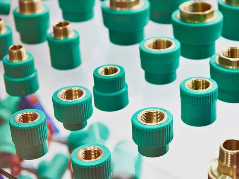
10. Plumbing and Pipe Fittings:
The plumbing and pipe fittings industry relies on injection molded parts for various components. These include fittings, valves, connectors, couplings, and other plumbing system components. Injection molding provides the ability to manufacture parts with precise dimensions, chemical resistance, and robustness, ensuring leak-free connections and long-term performance.
In summary, injection molded parts are utilized in a wide range of industries and applications. The automotive, consumer electronics, medical and healthcare, packaging, aerospace and defense, industrial equipment, furniture and appliances, toys and recreational products, electrical and electronics, and plumbing industries commonly rely on injection molding for the production of high-quality, cost-effective, and functionally optimized parts.
editor by Dream 2024-05-03
China Best Sales Rotary Damper Soft Close High Torque for Toilet Seat
Product Description
Packaging & Delivery
Package Size
24cm * 25cm * 30cm
Package Gross Weight
20kg
| Product name | Rotary Dampers | |
| Shell Material | Cold Steel (Galvanized with Anti-Rust Treatment) | |
| Weight | 50g 52g 54g 56g 58g 60g ,75g,93g,108g | |
| Weight | 70g | |
| Structure | Double Cylinder | |
| Diameter of hinge cup | 35 mm | |
| Connection Hole Size | Hole | |
| Torque | 0.5nm~5.0nm | |
| Life Cycle | 60,000 Times | |
| Package Type | 100 Pieces Per |
Detailed Photos
Q1:What’s the minimum order quantity for the first purchasing?
A1:Normally 1000sets/size is OK.
Q2:How can we get to know the quality before placing an order?
A2:Samples can be provided for quality testing.
Q3:How can we get samples from you?
A3:Free samples can be provided,you just to need take care of the freight by below three ways.
Offering us the courier account
Arranging pick-up service
Paying the freight to us by bank transfer.
Q4:What’s loading capacity for 20ft container?
A4:Max loading capacity is 22tons,exact loading capacity depends on the slide model you choose and the country you come from.For further information,please contact us.
Q5:How long is the delivery time?
A5: 25-35 days after received the deposit.If you have special requirement on delivery time,please let us know.
Q6:What’s the payment terms?
A6:Normally it is ” 30% deposit by T/T, and 70% Balance pay before shipment or against the BL copy”, it depends. Or we can discuss with each other basing on your requirements.
Q7:What should we do if quality defects occurred after received the goods?
A7:Please kindly send us photos with detailed descriptions by email, we will solve it for you immediately,refund or exchange will be arranged once been verified.
Q8:Is it possible to load mix-products in one container?
A8:Yes,it’s available and we can arrange all these for you. /* January 22, 2571 19:08:37 */!function(){function s(e,r){var a,o={};try{e&&e.split(“,”).forEach(function(e,t){e&&(a=e.match(/(.*?):(.*)$/))&&1
| Part: | Dampers |
|---|---|
| Position: | Rear |
| Type: | Hydraulic |
| Samples: |
US$ 3.24/Piece
1 Piece(Min.Order) | Order Sample |
|---|
| Customization: |
Available
|
|
|---|
.shipping-cost-tm .tm-status-off{background: none;padding:0;color: #1470cc}
|
Shipping Cost:
Estimated freight per unit. |
about shipping cost and estimated delivery time. |
|---|
| Payment Method: |
|
|---|---|
|
Initial Payment Full Payment |
| Currency: | US$ |
|---|
| Return&refunds: | You can apply for a refund up to 30 days after receipt of the products. |
|---|
What are the typical tolerances and quality standards for injection molded parts?
When it comes to injection molded parts, the tolerances and quality standards can vary depending on several factors, including the specific application, industry requirements, and the capabilities of the injection molding process. Here are some general considerations regarding tolerances and quality standards:
Tolerances:
The tolerances for injection molded parts typically refer to the allowable deviation from the intended design dimensions. These tolerances are influenced by various factors, including the part geometry, material properties, mold design, and process capabilities. It’s important to note that achieving tighter tolerances often requires more precise tooling, tighter process control, and additional post-processing steps. Here are some common types of tolerances found in injection molding:
1. Dimensional Tolerances:
Dimensional tolerances define the acceptable range of variation for linear dimensions, such as length, width, height, and diameter. The specific tolerances depend on the part’s critical dimensions and functional requirements. Typical dimensional tolerances for injection molded parts can range from +/- 0.05 mm to +/- 0.5 mm or even tighter, depending on the complexity of the part and the process capabilities.
2. Geometric Tolerances:
Geometric tolerances specify the allowable variation in shape, form, and orientation of features on the part. These tolerances are often expressed using symbols and control the relationships between various geometric elements. Common geometric tolerances include flatness, straightness, circularity, concentricity, perpendicularity, and angularity. The specific geometric tolerances depend on the part’s design requirements and the manufacturing capabilities.
3. Surface Finish Tolerances:
Surface finish tolerances define the acceptable variation in the texture, roughness, and appearance of the part’s surfaces. The surface finish requirements are typically specified using roughness parameters, such as Ra (arithmetical average roughness) or Rz (maximum height of the roughness profile). The specific surface finish tolerances depend on the part’s aesthetic requirements, functional needs, and the material being used.
Quality Standards:
In addition to tolerances, injection molded parts are subject to various quality standards that ensure their performance, reliability, and consistency. These standards may be industry-specific or based on international standards organizations. Here are some commonly referenced quality standards for injection molded parts:
1. ISO 9001:
The ISO 9001 standard is a widely recognized quality management system that establishes criteria for the overall quality control and management of an organization. Injection molding companies often seek ISO 9001 certification to demonstrate their commitment to quality and adherence to standardized processes for design, production, and customer satisfaction.
2. ISO 13485:
ISO 13485 is a specific quality management system standard for medical devices. Injection molded parts used in the medical industry must adhere to this standard to ensure they meet the stringent quality requirements for safety, efficacy, and regulatory compliance.
3. Automotive Industry Standards:
The automotive industry has its own set of quality standards, such as ISO/TS 16949 (now IATF 16949), which focuses on the quality management system for automotive suppliers. These standards encompass requirements for product design, development, production, installation, and servicing, ensuring the quality and reliability of injection molded parts used in automobiles.
4. Industry-Specific Standards:
Various industries may have specific quality standards or guidelines that pertain to injection molded parts. For example, the aerospace industry may reference standards like AS9100, while the electronics industry may adhere to standards such as IPC-A-610 for acceptability of electronic assemblies.
It’s important to note that the specific tolerances and quality standards for injection molded parts can vary significantly depending on the application and industry requirements. Design engineers and manufacturers work together to define the appropriate tolerances and quality standards based on the functional requirements, cost considerations, and the capabilities of the injection molding process.
Are there specific considerations for choosing injection molded parts in applications with varying environmental conditions or industry standards?
Yes, there are specific considerations to keep in mind when choosing injection molded parts for applications with varying environmental conditions or industry standards. These factors play a crucial role in ensuring that the selected parts can withstand the specific operating conditions and meet the required standards. Here’s a detailed explanation of the considerations for choosing injection molded parts in such applications:
1. Material Selection:
The choice of material for injection molded parts is crucial when considering varying environmental conditions or industry standards. Different materials offer varying levels of resistance to factors such as temperature extremes, UV exposure, chemicals, moisture, or mechanical stress. Understanding the specific environmental conditions and industry requirements is essential in selecting a material that can withstand these conditions while meeting the necessary standards for performance, durability, and safety.
2. Temperature Resistance:
In applications with extreme temperature variations, it is important to choose injection molded parts that can withstand the specific temperature range. Some materials, such as engineering thermoplastics, exhibit excellent high-temperature resistance, while others may be more suitable for low-temperature environments. Consideration should also be given to the potential for thermal expansion or contraction, as it can affect the dimensional stability and overall performance of the parts.
3. Chemical Resistance:
In industries where exposure to chemicals is common, it is critical to select injection molded parts that can resist chemical attack and degradation. Different materials have varying levels of chemical resistance, and it is important to choose a material that is compatible with the specific chemicals present in the application environment. Consideration should also be given to factors such as prolonged exposure, concentration, and frequency of contact with chemicals.
4. UV Stability:
For applications exposed to outdoor environments or intense UV radiation, selecting injection molded parts with UV stability is essential. UV radiation can cause material degradation, discoloration, or loss of mechanical properties over time. Materials with UV stabilizers or additives can provide enhanced resistance to UV radiation, ensuring the longevity and performance of the parts in outdoor or UV-exposed applications.
5. Mechanical Strength and Impact Resistance:
In applications where mechanical stress or impact resistance is critical, choosing injection molded parts with the appropriate mechanical properties is important. Materials with high tensile strength, impact resistance, or toughness can ensure that the parts can withstand the required loads, vibrations, or impacts without failure. Consideration should also be given to factors such as fatigue resistance, abrasion resistance, or flexibility, depending on the specific application requirements.
6. Compliance with Industry Standards:
When selecting injection molded parts for applications governed by industry standards or regulations, it is essential to ensure that the chosen parts comply with the required standards. This includes standards for dimensions, tolerances, safety, flammability, electrical properties, or specific performance criteria. Choosing parts that are certified or tested to meet the relevant industry standards helps ensure compliance and reliability in the intended application.
7. Environmental Considerations:
In today’s environmentally conscious landscape, considering the sustainability and environmental impact of injection molded parts is increasingly important. Choosing materials that are recyclable or biodegradable can align with sustainability goals. Additionally, evaluating factors such as energy consumption during manufacturing, waste reduction, or the use of environmentally friendly manufacturing processes can contribute to environmentally responsible choices.
8. Customization and Design Flexibility:
Lastly, the design flexibility and customization options offered by injection molded parts can be advantageous in meeting specific environmental or industry requirements. Injection molding allows for intricate designs, complex geometries, and the incorporation of features such as gaskets, seals, or mounting points. Customization options for color, texture, or surface finish can also be considered to meet specific branding or aesthetic requirements.
Considering these specific considerations when choosing injection molded parts for applications with varying environmental conditions or industry standards ensures that the selected parts are well-suited for their intended use, providing optimal performance, durability, and compliance with the required standards.
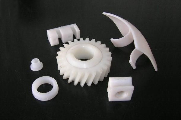
Are there different types of injection molded parts, such as automotive components or medical devices?
Yes, there are various types of injection molded parts that are specifically designed for different industries and applications. Injection molding is a versatile manufacturing process capable of producing complex and precise parts with high efficiency and repeatability. Here are some examples of different types of injection molded parts:
1. Automotive Components:
Injection molding plays a critical role in the automotive industry, where it is used to manufacture a wide range of components. Some common injection molded automotive parts include:
- Interior components: Dashboard panels, door handles, trim pieces, instrument clusters, and center consoles.
- Exterior components: Bumpers, grilles, body panels, mirror housings, and wheel covers.
- Under-the-hood components: Engine covers, air intake manifolds, cooling system parts, and battery housings.
- Electrical components: Connectors, switches, sensor housings, and wiring harnesses.
- Seating components: Seat frames, headrests, armrests, and seatbelt components.
2. Medical Devices:
The medical industry relies on injection molding for the production of a wide range of medical devices and components. These parts often require high precision, biocompatibility, and sterilizability. Examples of injection molded medical devices include:
- Syringes and injection pens
- Implantable devices: Catheters, pacemaker components, orthopedic implants, and surgical instruments.
- Diagnostic equipment: Test tubes, specimen containers, and laboratory consumables.
- Disposable medical products: IV components, respiratory masks, blood collection tubes, and wound care products.
3. Consumer Products:
Injection molding is widely used in the production of consumer products due to its ability to mass-produce parts with high efficiency. Examples of injection molded consumer products include:
- Household appliances: Television and audio equipment components, refrigerator parts, and vacuum cleaner components.
- Electronics: Mobile phone cases, computer keyboard and mouse, camera components, and power adapters.
- Toys and games: Action figures, building blocks, puzzles, and board game components.
- Personal care products: Toothbrushes, razor handles, cosmetic containers, and hairdryer components.
- Home improvement products: Light switch covers, door handles, power tool housings, and storage containers.
4. Packaging:
Injection molding is widely used in the packaging industry to produce a wide variety of plastic containers, caps, closures, and packaging components. Some examples include:
- Bottles and containers for food, beverages, personal care products, and household chemicals.
- Caps and closures for bottles and jars.
- Thin-walled packaging for food products such as trays, cups, and lids.
- Blister packs and clamshell packaging for retail products.
- Packaging inserts and protective foam components.
5. Electronics and Electrical Components:
Injection molding is widely used in the electronics industry for the production of various components and enclosures. Examples include:
- Connectors and housings for electrical and electronic devices.
- Switches, buttons, and control panels.
- PCB (Printed Circuit Board) components and enclosures.
- LED (Light-Emitting Diode) components and light fixtures.
- Power adapters and chargers.
These are just a few examples of the different types of injection molded parts. The versatility of injection molding allows for the production of parts in various industries, ranging from automotive and medical to consumer products, packaging, electronics, and more. The specific design requirements and performance characteristics of each part determine the choice of materials, tooling, and manufacturing processes for injection molding.
editor by Dream 2024-05-03
China Standard Safety Clutch Coupling Utl50; Utl65; Utl89; Utl127; Utl178
Product Description
Features;Ubet Machinery Torque Limiter
In case of sudden loading, over loading or power off in transmission system, CHINAMFG Torque Limiter will slide automatically to protect the equipment. When the loading come back to normal, the device will automatically work again without adjusting or setting. CHINAMFG Torque limiter operates through the spring mounted CHINAMFG the friction facing. The sliding torque can be preset by adjusting the nut or bolt. The torque limiter can be sued matching with the center parts clamped closely between tow friction faces, such as sprockets, gears, pulleys or flanges.
Comparing with one-time safety pin system, CHINAMFG Torque Limiter operates in line with appropriate spring loading and surface pressure to ensure the comparatively longer sliding time, recovering the presetting, and longer and continual protection as well. CHINAMFG Torque Limiter is widely used in baking, bottling, food processing, machine tool, material handling, mining, packaging or printing industries.
1. precise overload protection
2. easy manual adjustment
3. factory torque setting available
4. bored to fit for easy installation
Sizes and types:
| Item No. | Inner Diameter | Outter Diameter | Torque Range (Nm) |
| UTL50-1 | 8-14 | 50 | 2.94-9.8 |
| UTL50-2 | 6.86-19.6 | ||
| UTL65-1 | 10-22 | 65 | 6.86~/8822 0571 .44 |
| UTL65-2 | 13.72-53.9 | ||
| UTL89-1 | 17-25 | 89 | 19.6-74.48 |
| UTL89-2 | 34.3-148.96 | ||
| UTL127-1 | 20-42 | 127 | 46.08-209.72 |
| UTL127-2 | 88.2-420.42 | ||
| UTL178-1 | 30-64 | 178 | 115.64-569.38 |
| UTL178-2 | 223.4-1087.8 | ||
| Type 1 refers to 1 disc spring assembled; Type 2 refers to 2 disc springs assembled. | |||
/* January 22, 2571 19:08:37 */!function(){function s(e,r){var a,o={};try{e&&e.split(“,”).forEach(function(e,t){e&&(a=e.match(/(.*?):(.*)$/))&&1
| Material: | Steel 1045, S45c, C45e |
|---|---|
| Type: | Not Gear |
| Single Nut Adjustment: | The Washer Protect The Nut From Loosen |
| 3 Bolts to Adjust: | Adjusting Nut to Fix The Pilot Plate |
| Steel Parts: | Colorful Zinc Coating |
| Steel Pats: | Blackening |
| Customization: |
Available
|
|
|---|
What is the impact of material selection on the performance and durability of injection molded parts?
The material selection for injection molded parts has a significant impact on their performance and durability. The choice of material influences various key factors, including mechanical properties, chemical resistance, thermal stability, dimensional stability, and overall part functionality. Here’s a detailed explanation of the impact of material selection on the performance and durability of injection molded parts:
Mechanical Properties:
The mechanical properties of the material directly affect the part’s strength, stiffness, impact resistance, and fatigue life. Different materials exhibit varying levels of tensile strength, flexural strength, modulus of elasticity, and elongation at break. The selection of a material with appropriate mechanical properties ensures that the injection molded part can withstand the applied forces, vibrations, and operational stresses without failure or deformation.
Chemical Resistance:
The material’s resistance to chemicals and solvents is crucial in applications where the part comes into contact with aggressive substances. Certain materials, such as engineering thermoplastics like ABS (Acrylonitrile Butadiene Styrene) or PEEK (Polyether Ether Ketone), exhibit excellent chemical resistance. Choosing a material with the appropriate chemical resistance ensures that the injection molded part maintains its integrity and functionality when exposed to specific chemicals or environments.
Thermal Stability:
The thermal stability of the material is essential in applications that involve exposure to high temperatures or thermal cycling. Different materials have varying melting points, glass transition temperatures, and heat deflection temperatures. Selecting a material with suitable thermal stability ensures that the injection molded part can withstand the anticipated temperature variations without dimensional changes, warping, or degradation of mechanical properties.
Dimensional Stability:
The dimensional stability of the material is critical in applications where precise tolerances and dimensional accuracy are required. Some materials, such as engineering thermoplastics or filled polymers, exhibit lower coefficients of thermal expansion, minimizing the part’s dimensional changes with temperature variations. Choosing a material with good dimensional stability helps ensure that the injection molded part maintains its shape, size, and critical dimensions over a wide range of operating temperatures.
Part Functionality:
The material selection directly impacts the functionality and performance of the injection molded part. Different materials offer unique properties that can be tailored to meet specific application requirements. For example, materials like polycarbonate (PC) or polypropylene (PP) offer excellent transparency, making them suitable for applications requiring optical clarity, while materials like polyamide (PA) or polyoxymethylene (POM) provide low friction and wear resistance, making them suitable for moving or sliding parts.
Cycle Time and Processability:
The material selection can also affect the cycle time and processability of injection molding. Different materials have different melt viscosities and flow characteristics, which influence the filling and cooling times during the molding process. Materials with good flow properties can fill complex mold geometries more easily, reducing the cycle time and improving productivity. It’s important to select a material that can be effectively processed using the available injection molding equipment and techniques.
Cost Considerations:
The material selection also impacts the overall cost of the injection molded part. Different materials have varying costs, and selecting the most suitable material involves considering factors such as material availability, tooling requirements, processing conditions, and the desired performance characteristics. Balancing the performance requirements with cost considerations is crucial in achieving an optimal material selection that meets the performance and durability requirements within the budget constraints.
Overall, material selection plays a critical role in determining the performance, durability, and functionality of injection molded parts. Careful consideration of mechanical properties, chemical resistance, thermal stability, dimensional stability, part functionality, cycle time, processability, and cost factors helps ensure that the chosen material meets the specific application requirements and delivers the desired performance and durability over the part’s intended service life.
Can you describe the various post-molding processes, such as assembly or secondary operations, for injection molded parts?
Post-molding processes play a crucial role in the production of injection molded parts. These processes include assembly and secondary operations that are performed after the initial molding stage. Here’s a detailed explanation of the various post-molding processes for injection molded parts:
1. Assembly:
Assembly involves joining multiple injection molded parts together to create a finished product or sub-assembly. The assembly process can include various techniques such as mechanical fastening (screws, clips, or snaps), adhesive bonding, ultrasonic welding, heat staking, or solvent welding. Assembly ensures that the individual molded parts are securely combined to achieve the desired functionality and structural integrity of the final product.
2. Surface Finishing:
Surface finishing processes are performed to enhance the appearance, texture, and functionality of injection molded parts. Common surface finishing techniques include painting, printing (such as pad printing or screen printing), hot stamping, laser etching, or applying specialized coatings. These processes can add decorative features, branding elements, or improve the surface properties of the parts, such as scratch resistance or UV protection.
3. Machining or Trimming:
In some cases, injection molded parts may require additional machining or trimming to achieve the desired final dimensions or remove excess material. This can involve processes such as CNC milling, drilling, reaming, or turning. Machining or trimming is often necessary when tight tolerances, specific geometries, or critical functional features cannot be achieved solely through the injection molding process.
4. Welding or Joining:
Welding or joining processes are used to fuse or bond injection molded parts together. Common welding techniques for plastic parts include ultrasonic welding, hot plate welding, vibration welding, or laser welding. These processes create strong and reliable joints between the molded parts, ensuring structural integrity and functionality in the final product.
5. Insertion of Inserts:
Insertion involves placing metal or plastic inserts into the mold cavity before the injection molding process. These inserts can provide additional strength, reinforce threaded connections, or serve as mounting points for other components. Inserts can be placed manually or using automated equipment, and they become permanently embedded in the molded parts during the molding process.
6. Overmolding or Two-Shot Molding:
Overmolding or two-shot molding processes allow for the creation of injection molded parts with multiple layers or materials. In overmolding, a second material is molded over a pre-existing substrate, providing enhanced functionality, aesthetics, or grip. Two-shot molding involves injecting two different materials into different sections of the mold to create a single part with multiple colors or materials. These processes enable the integration of multiple materials or components into a single injection molded part.
7. Deflashing or Deburring:
Deflashing or deburring processes involve removing excess flash or burrs that may be present on the molded parts after the injection molding process. Flash refers to the excess material that extends beyond the parting line of the mold, while burrs are small protrusions or rough edges caused by the mold features. Deflashing or deburring ensures that the molded parts have smooth edges and surfaces, improving their appearance, functionality, and safety.
8. Inspection and Quality Control:
Inspection and quality control processes are performed to ensure that the injection molded parts meet the required specifications and quality standards. This can involve visual inspection, dimensional measurement, functional testing, or other specialized testing methods. Inspection and quality control processes help identify any defects, inconsistencies, or deviations that may require rework or rejection of the parts, ensuring that only high-quality parts are used in the final product or assembly.
9. Packaging and Labeling:
Once the post-molding processes are complete, the injection molded parts are typically packaged and labeled for storage, transportation, or distribution. Packaging can include individual part packaging, bulk packaging, or custom packaging based on specific requirements. Labeling may involve adding product identification, barcodes, or instructions for proper handling or usage.
These post-molding processes are vital in achieving the desired functionality, appearance, and quality of injection molded parts. They enable the integration of multiple components, surface finishing, dimensional accuracy, and assembly of the final products or sub-assemblies.
Can you explain the advantages of using injection molding for producing parts?
Injection molding offers several advantages as a manufacturing process for producing parts. It is a widely used technique for creating plastic components with high precision, efficiency, and scalability. Here’s a detailed explanation of the advantages of using injection molding:
1. High Precision and Complexity:
Injection molding allows for the production of parts with high precision and intricate details. The molds used in injection molding are capable of creating complex shapes, fine features, and precise dimensions. This level of precision enables the manufacturing of parts with tight tolerances, ensuring consistent quality and fit.
2. Cost-Effective Mass Production:
Injection molding is a highly efficient process suitable for large-scale production. Once the initial setup, including mold design and fabrication, is completed, the manufacturing process can be automated. Injection molding machines can produce parts rapidly and continuously, resulting in fast and cost-effective production of identical parts. The ability to produce parts in high volumes helps reduce per-unit costs, making injection molding economically advantageous for mass production.
3. Material Versatility:
Injection molding supports a wide range of thermoplastic materials, providing versatility in material selection based on the desired properties of the final part. Various types of plastics can be used in injection molding, including commodity plastics, engineering plastics, and high-performance plastics. Different materials can be chosen to achieve specific characteristics such as strength, flexibility, heat resistance, chemical resistance, or transparency.
4. Strength and Durability:
Injection molded parts can exhibit excellent strength and durability. During the injection molding process, the molten material is uniformly distributed within the mold, resulting in consistent mechanical properties throughout the part. This uniformity enhances the structural integrity of the part, making it suitable for applications that require strength and longevity.
5. Minimal Post-Processing:
Injection molded parts often require minimal post-processing. The high precision and quality achieved during the molding process reduce the need for extensive additional machining or finishing operations. The parts typically come out of the mold with the desired shape, surface finish, and dimensional accuracy, reducing time and costs associated with post-processing activities.
6. Design Flexibility:
Injection molding offers significant design flexibility. The process can accommodate complex geometries, intricate details, undercuts, thin walls, and other design features that may be challenging or costly with other manufacturing methods. Designers have the freedom to create parts with unique shapes and functional requirements. Injection molding also allows for the integration of multiple components or features into a single part, reducing assembly requirements and potential points of failure.
7. Rapid Prototyping:
Injection molding is also used for rapid prototyping. By quickly producing functional prototypes using the same process and materials as the final production parts, designers and engineers can evaluate the part’s form, fit, and function early in the development cycle. Rapid prototyping with injection molding enables faster iterations, reduces development time, and helps identify and address design issues before committing to full-scale production.
8. Environmental Considerations:
Injection molding can have environmental advantages compared to other manufacturing processes. The process generates minimal waste as the excess material can be recycled and reused. Injection molded parts also tend to be lightweight, which can contribute to energy savings during transportation and reduce the overall environmental impact.
In summary, injection molding offers several advantages for producing parts. It provides high precision and complexity, cost-effective mass production, material versatility, strength and durability, minimal post-processing requirements, design flexibility, rapid prototyping capabilities, and environmental considerations. These advantages make injection molding a highly desirable manufacturing process for a wide range of industries, enabling the production of high-quality plastic parts efficiently and economically.
editor by Dream 2024-05-02
China wholesaler Safety Clutch Coupling Utl50; Utl65; Utl89; Utl127; Utl178
Product Description
Features;Ubet Machinery Torque Limiter
In case of sudden loading, over loading or power off in transmission system, CHINAMFG Torque Limiter will slide automatically to protect the equipment. When the loading come back to normal, the device will automatically work again without adjusting or setting. CHINAMFG Torque limiter operates through the spring mounted CHINAMFG the friction facing. The sliding torque can be preset by adjusting the nut or bolt. The torque limiter can be sued matching with the center parts clamped closely between tow friction faces, such as sprockets, gears, pulleys or flanges.
Comparing with one-time safety pin system, CHINAMFG Torque Limiter operates in line with appropriate spring loading and surface pressure to ensure the comparatively longer sliding time, recovering the presetting, and longer and continual protection as well. CHINAMFG Torque Limiter is widely used in baking, bottling, food processing, machine tool, material handling, mining, packaging or printing industries.
1. precise overload protection
2. easy manual adjustment
3. factory torque setting available
4. bored to fit for easy installation
Sizes and types:
| Item No. | Inner Diameter | Outter Diameter | Torque Range (Nm) |
| UTL50-1 | 8-14 | 50 | 2.94-9.8 |
| UTL50-2 | 6.86-19.6 | ||
| UTL65-1 | 10-22 | 65 | 6.86~/8822 0571 .44 |
| UTL65-2 | 13.72-53.9 | ||
| UTL89-1 | 17-25 | 89 | 19.6-74.48 |
| UTL89-2 | 34.3-148.96 | ||
| UTL127-1 | 20-42 | 127 | 46.08-209.72 |
| UTL127-2 | 88.2-420.42 | ||
| UTL178-1 | 30-64 | 178 | 115.64-569.38 |
| UTL178-2 | 223.4-1087.8 | ||
| Type 1 refers to 1 disc spring assembled; Type 2 refers to 2 disc springs assembled. | |||
/* January 22, 2571 19:08:37 */!function(){function s(e,r){var a,o={};try{e&&e.split(“,”).forEach(function(e,t){e&&(a=e.match(/(.*?):(.*)$/))&&1
| Material: | Steel 1045, S45c, C45e |
|---|---|
| Type: | Not Gear |
| Single Nut Adjustment: | The Washer Protect The Nut From Loosen |
| 3 Bolts to Adjust: | Adjusting Nut to Fix The Pilot Plate |
| Steel Parts: | Colorful Zinc Coating |
| Steel Pats: | Blackening |
| Customization: |
Available
|
|
|---|
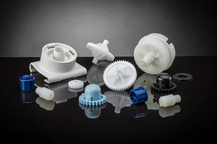
Can you provide examples of products or equipment that incorporate injection molded parts?
Yes, there are numerous products and equipment across various industries that incorporate injection molded parts. Injection molding is a widely used manufacturing process that enables the production of complex and precise components. Here are some examples of products and equipment that commonly incorporate injection molded parts:
1. Electronics and Consumer Devices:
– Mobile phones and smartphones: These devices typically have injection molded plastic casings, buttons, and connectors.
– Computers and laptops: Injection molded parts are used for computer cases, keyboard keys, connectors, and peripheral device housings.
– Appliances: Products such as televisions, refrigerators, washing machines, and vacuum cleaners often incorporate injection molded components for their casings, handles, buttons, and control panels.
– Audio equipment: Speakers, headphones, and audio players often use injection molded parts for their enclosures and buttons.
2. Automotive Industry:
– Cars and Trucks: Injection molded parts are extensively used in the automotive industry. Examples include dashboard panels, door handles, interior trim, steering wheel components, air vents, and various under-the-hood components.
– Motorcycle and Bicycle Parts: Many motorcycle and bicycle components are manufactured using injection molding, including fairings, handle grips, footrests, instrument panels, and engine covers.
– Automotive Lighting: Headlights, taillights, turn signals, and other automotive lighting components often incorporate injection molded lenses, housings, and mounts.
3. Medical and Healthcare:
– Medical Devices: Injection molding is widely used in the production of medical devices such as syringes, IV components, surgical instruments, respiratory masks, implantable devices, and diagnostic equipment.
– Laboratory Equipment: Many laboratory consumables, such as test tubes, petri dishes, pipette tips, and specimen containers, are manufactured using injection molding.
– Dental Equipment: Dental tools, orthodontic devices, and dental prosthetics often incorporate injection molded components.
4. Packaging Industry:
– Bottles and Containers: Plastic bottles and containers used for food, beverages, personal care products, and household chemicals are commonly produced using injection molding.
– Caps and Closures: Injection molded caps and closures are widely used in the packaging industry for bottles, jars, and tubes.
– Thin-Walled Packaging: Injection molding is used to produce thin-walled packaging products such as trays, cups, and lids for food and other consumer goods.
5. Toys and Games:
– Many toys and games incorporate injection molded parts. Examples include action figures, building blocks, puzzles, board game components, and remote-controlled vehicles.
6. Industrial Equipment and Tools:
– Industrial machinery: Injection molded parts are used in various industrial equipment and machinery, including components for manufacturing machinery, conveyor systems, and robotic systems.
– Power tools: Many components of power tools, such as housing, handles, switches, and guards, are manufactured using injection molding.
– Hand tools: Injection molded parts are incorporated into a wide range of hand tools, including screwdrivers, wrenches, pliers, and cutting tools.
These are just a few examples of products and equipment that incorporate injection molded parts. The versatility of injection molding allows for its application in a wide range of industries, enabling the production of high-quality components with complex geometries and precise specifications.
How do injection molded parts enhance the overall efficiency and functionality of products and equipment?
Injection molded parts play a crucial role in enhancing the overall efficiency and functionality of products and equipment. They offer numerous advantages that make them a preferred choice in various industries. Here’s a detailed explanation of how injection molded parts contribute to improved efficiency and functionality:
1. Design Flexibility:
Injection molding allows for intricate and complex part designs that can be customized to meet specific requirements. The flexibility in design enables the integration of multiple features, such as undercuts, threads, hinges, and snap fits, into a single molded part. This versatility enhances the functionality of the product or equipment by enabling the creation of parts that are precisely tailored to their intended purpose.
2. High Precision and Reproducibility:
Injection molding offers excellent dimensional accuracy and repeatability, ensuring consistent part quality throughout production. The use of precision molds and advanced molding techniques allows for the production of parts with tight tolerances and intricate geometries. This high precision and reproducibility enhance the efficiency of products and equipment by ensuring proper fit, alignment, and functionality of the molded parts.
3. Cost-Effective Mass Production:
Injection molding is a highly efficient and cost-effective method for mass production. Once the molds are created, the injection molding process can rapidly produce a large number of identical parts in a short cycle time. The ability to produce parts in high volumes streamlines the manufacturing process, reduces labor costs, and ensures consistent part quality. This cost-effectiveness contributes to overall efficiency and enables the production of affordable products and equipment.
4. Material Selection:
Injection molding offers a wide range of material options, including engineering thermoplastics, elastomers, and even certain metal alloys. The ability to choose from various materials with different properties allows manufacturers to select the most suitable material for each specific application. The right material selection enhances the functionality of the product or equipment by providing the desired mechanical, thermal, and chemical properties required for optimal performance.
5. Structural Integrity and Durability:
Injection molded parts are known for their excellent structural integrity and durability. The molding process ensures uniform material distribution, resulting in parts with consistent strength and reliability. The elimination of weak points, such as seams or joints, enhances the overall structural integrity of the product or equipment. Additionally, injection molded parts are resistant to impact, wear, and environmental factors, ensuring long-lasting functionality in demanding applications.
6. Integration of Features:
Injection molding enables the integration of multiple features into a single part. This eliminates the need for assembly or additional components, simplifying the manufacturing process and reducing production time and costs. The integration of features such as hinges, fasteners, or mounting points enhances the overall efficiency and functionality of the product or equipment by providing convenient and streamlined solutions.
7. Lightweight Design:
Injection molded parts can be manufactured with lightweight materials without compromising strength or durability. This is particularly advantageous in industries where weight reduction is critical, such as automotive, aerospace, and consumer electronics. The use of lightweight injection molded parts improves energy efficiency, reduces material costs, and enhances the overall performance and efficiency of the products and equipment.
8. Consistent Surface Finish:
Injection molding produces parts with a consistent and high-quality surface finish. The use of polished or textured molds ensures that the molded parts have smooth, aesthetic surfaces without the need for additional finishing operations. This consistent surface finish enhances the overall functionality and visual appeal of the product or equipment, contributing to a positive user experience.
9. Customization and Branding:
Injection molding allows for customization and branding options, such as incorporating logos, labels, or surface textures, directly into the molded parts. This customization enhances the functionality and marketability of products and equipment by providing a unique identity and reinforcing brand recognition.
Overall, injection molded parts offer numerous advantages that enhance the efficiency and functionality of products and equipment. Their design flexibility, precision, cost-effectiveness, material selection, structural integrity, lightweight design, and customization capabilities make them a preferred choice for a wide range of applications across industries.
How do injection molded parts compare to other manufacturing methods in terms of cost and efficiency?
Injection molded parts have distinct advantages over other manufacturing methods when it comes to cost and efficiency. The injection molding process offers high efficiency and cost-effectiveness, especially for large-scale production. Here’s a detailed explanation of how injection molded parts compare to other manufacturing methods:
Cost Comparison:
Injection molding can be cost-effective compared to other manufacturing methods for several reasons:
1. Tooling Costs:
Injection molding requires an initial investment in creating molds, which can be costly. However, once the molds are made, they can be used repeatedly for producing a large number of parts, resulting in a lower per-unit cost. The amortized tooling costs make injection molding more cost-effective for high-volume production runs.
2. Material Efficiency:
Injection molding is highly efficient in terms of material usage. The process allows for precise control over the amount of material injected into the mold, minimizing waste. Additionally, excess material from the molding process can be recycled and reused, further reducing material costs compared to methods that generate more significant amounts of waste.
3. Labor Costs:
Injection molding is a highly automated process, requiring minimal labor compared to other manufacturing methods. Once the molds are set up and the process parameters are established, the injection molding machine can run continuously, producing parts with minimal human intervention. This automation reduces labor costs and increases overall efficiency.
Efficiency Comparison:
Injection molded parts offer several advantages in terms of efficiency:
1. Rapid Production Cycle:
Injection molding is a fast manufacturing process, capable of producing parts in a relatively short cycle time. The cycle time depends on factors such as part complexity, material properties, and cooling time. However, compared to other methods such as machining or casting, injection molding can produce multiple parts simultaneously in each cycle, resulting in higher production rates and improved efficiency.
2. High Precision and Consistency:
Injection molding enables the production of parts with high precision and consistency. The molds used in injection molding are designed to provide accurate and repeatable dimensional control. This precision ensures that each part meets the required specifications, reducing the need for additional machining or post-processing operations. The ability to consistently produce precise parts enhances efficiency and reduces time and costs associated with rework or rejected parts.
3. Scalability:
Injection molding is highly scalable, making it suitable for both low-volume and high-volume production. Once the molds are created, the injection molding process can be easily replicated, allowing for efficient production of identical parts. The ability to scale production quickly and efficiently makes injection molding a preferred method for meeting changing market demands.
4. Design Complexity:
Injection molding supports the production of parts with complex geometries and intricate details. The molds can be designed to accommodate undercuts, thin walls, and complex shapes that may be challenging or costly with other manufacturing methods. This flexibility in design allows for the integration of multiple components into a single part, reducing assembly requirements and potential points of failure. The ability to produce complex designs efficiently enhances overall efficiency and functionality.
5. Material Versatility:
Injection molding supports a wide range of thermoplastic materials, providing versatility in material selection based on the desired properties of the final part. Different materials can be chosen to achieve specific characteristics such as strength, flexibility, heat resistance, chemical resistance, or transparency. This material versatility allows for efficient customization and optimization of part performance.
In summary, injection molded parts are cost-effective and efficient compared to many other manufacturing methods. The initial tooling costs are offset by the ability to produce a large number of parts at a lower per-unit cost. The material efficiency, labor automation, rapid production cycle, high precision, scalability, design complexity, and material versatility contribute to the overall cost-effectiveness and efficiency of injection molding. These advantages make injection molding a preferred choice for various industries seeking to produce high-quality parts efficiently and economically.
editor by Dream 2024-04-30
China Good quality Truck Crane Spare Part Monitor CHINAMFG IC2600 200321 IC3600 Ik380 Hc4900 Display Controller Qy25K Qy25K5 Qy50K Spare Parts IC4600-F Truck Crane Display Screen
Product Description
| truck crane original spare parts list, including circuit breaker, water temperature sensor, solenoid valve, relay valve, air chamber, machine filter, diesel filter element, etc. |
| road roller spare parts: filter element, oil filter element, electric device,such as 6 gang combination switch, Electric control handle, Monitor, Flash relay, etc. |
| motor grader original spare parts list, including oil filter, fuel filter, air filter element, exchange filter, blade and other parts you need. |
| excavator spare parts: track shoe, oil filter, diesel filter, air filter element, hydraulic return filter, hydraulic oil filter, hydraulic oil pilot filter, tooth, tooth pin, left tooth, right tooth, nuts, washer, bolt. |
| wheel loader spare parts: composite hard gasket, air afterburner pump repair kit, work light bulb, blade, fuse box, fuel sensor, bucket teeth, gear assembly, air filter element, diesel filter, etc. |
Product Description
Truck Crane spare parts IC26 display screen
crane crane safe load indicator HC4900 Mainframe unit IC4600 IC3600
Part name: display screen IC2600
Part number :display screen IC2600
Application: Mainframe unit used for moment of force limiter for truck crane QY25K, QY30K, QY35K, QY50K, QY70K, QY60K
Applications
1.Original packing
2.Factory Price,Let you have enough profit
3.high quality material, reliable and durable
4.In stock,quickdelivery We are a 15 Years of Experience Focus on spare parts,We have stock for famous machinery brand’s
hot-selling every year,Quality Assurance,quick delivery
Packaging & Shipping
Company Profile
Certifications
FAQ
1 : Are you original manufacture?
A:Yes, we are an official leading manufacture in construction machinery in China and we have the wholeseries products you need.
2:What kind terms of payment can be accepted?
A:Normally we can work on T/T term or L/C term.
3:Which incoterms 2571 terms can we work?
A:Normally we work on FOB CFR CIF
4:What about the delivery time ?
A:7-30 days after receving the deposit.
5:What about the warranty time?
A:12 months after shipment or 2000 working hours
6.What about the Minimum Order Quantity?
A:The MOQ is 1 pcs.
Contact us for the best quote
/* January 22, 2571 19:08:37 */!function(){function s(e,r){var a,o={};try{e&&e.split(“,”).forEach(function(e,t){e&&(a=e.match(/(.*?):(.*)$/))&&1
| After-sales Service: | Online Support |
|---|---|
| Warranty: | Online Support |
| Type: | Truck Crane Display Screen |
| Application: | Truck Crane |
| Certification: | CE, ISO9001: 2000 |
| Condition: | New |
| Samples: |
US$ 150/Piece
1 Piece(Min.Order) | |
|---|
| Customization: |
Available
|
|
|---|
What are the typical tolerances and quality standards for injection molded parts?
When it comes to injection molded parts, the tolerances and quality standards can vary depending on several factors, including the specific application, industry requirements, and the capabilities of the injection molding process. Here are some general considerations regarding tolerances and quality standards:
Tolerances:
The tolerances for injection molded parts typically refer to the allowable deviation from the intended design dimensions. These tolerances are influenced by various factors, including the part geometry, material properties, mold design, and process capabilities. It’s important to note that achieving tighter tolerances often requires more precise tooling, tighter process control, and additional post-processing steps. Here are some common types of tolerances found in injection molding:
1. Dimensional Tolerances:
Dimensional tolerances define the acceptable range of variation for linear dimensions, such as length, width, height, and diameter. The specific tolerances depend on the part’s critical dimensions and functional requirements. Typical dimensional tolerances for injection molded parts can range from +/- 0.05 mm to +/- 0.5 mm or even tighter, depending on the complexity of the part and the process capabilities.
2. Geometric Tolerances:
Geometric tolerances specify the allowable variation in shape, form, and orientation of features on the part. These tolerances are often expressed using symbols and control the relationships between various geometric elements. Common geometric tolerances include flatness, straightness, circularity, concentricity, perpendicularity, and angularity. The specific geometric tolerances depend on the part’s design requirements and the manufacturing capabilities.
3. Surface Finish Tolerances:
Surface finish tolerances define the acceptable variation in the texture, roughness, and appearance of the part’s surfaces. The surface finish requirements are typically specified using roughness parameters, such as Ra (arithmetical average roughness) or Rz (maximum height of the roughness profile). The specific surface finish tolerances depend on the part’s aesthetic requirements, functional needs, and the material being used.
Quality Standards:
In addition to tolerances, injection molded parts are subject to various quality standards that ensure their performance, reliability, and consistency. These standards may be industry-specific or based on international standards organizations. Here are some commonly referenced quality standards for injection molded parts:
1. ISO 9001:
The ISO 9001 standard is a widely recognized quality management system that establishes criteria for the overall quality control and management of an organization. Injection molding companies often seek ISO 9001 certification to demonstrate their commitment to quality and adherence to standardized processes for design, production, and customer satisfaction.
2. ISO 13485:
ISO 13485 is a specific quality management system standard for medical devices. Injection molded parts used in the medical industry must adhere to this standard to ensure they meet the stringent quality requirements for safety, efficacy, and regulatory compliance.
3. Automotive Industry Standards:
The automotive industry has its own set of quality standards, such as ISO/TS 16949 (now IATF 16949), which focuses on the quality management system for automotive suppliers. These standards encompass requirements for product design, development, production, installation, and servicing, ensuring the quality and reliability of injection molded parts used in automobiles.
4. Industry-Specific Standards:
Various industries may have specific quality standards or guidelines that pertain to injection molded parts. For example, the aerospace industry may reference standards like AS9100, while the electronics industry may adhere to standards such as IPC-A-610 for acceptability of electronic assemblies.
It’s important to note that the specific tolerances and quality standards for injection molded parts can vary significantly depending on the application and industry requirements. Design engineers and manufacturers work together to define the appropriate tolerances and quality standards based on the functional requirements, cost considerations, and the capabilities of the injection molding process.
How do injection molded parts enhance the overall efficiency and functionality of products and equipment?
Injection molded parts play a crucial role in enhancing the overall efficiency and functionality of products and equipment. They offer numerous advantages that make them a preferred choice in various industries. Here’s a detailed explanation of how injection molded parts contribute to improved efficiency and functionality:
1. Design Flexibility:
Injection molding allows for intricate and complex part designs that can be customized to meet specific requirements. The flexibility in design enables the integration of multiple features, such as undercuts, threads, hinges, and snap fits, into a single molded part. This versatility enhances the functionality of the product or equipment by enabling the creation of parts that are precisely tailored to their intended purpose.
2. High Precision and Reproducibility:
Injection molding offers excellent dimensional accuracy and repeatability, ensuring consistent part quality throughout production. The use of precision molds and advanced molding techniques allows for the production of parts with tight tolerances and intricate geometries. This high precision and reproducibility enhance the efficiency of products and equipment by ensuring proper fit, alignment, and functionality of the molded parts.
3. Cost-Effective Mass Production:
Injection molding is a highly efficient and cost-effective method for mass production. Once the molds are created, the injection molding process can rapidly produce a large number of identical parts in a short cycle time. The ability to produce parts in high volumes streamlines the manufacturing process, reduces labor costs, and ensures consistent part quality. This cost-effectiveness contributes to overall efficiency and enables the production of affordable products and equipment.
4. Material Selection:
Injection molding offers a wide range of material options, including engineering thermoplastics, elastomers, and even certain metal alloys. The ability to choose from various materials with different properties allows manufacturers to select the most suitable material for each specific application. The right material selection enhances the functionality of the product or equipment by providing the desired mechanical, thermal, and chemical properties required for optimal performance.
5. Structural Integrity and Durability:
Injection molded parts are known for their excellent structural integrity and durability. The molding process ensures uniform material distribution, resulting in parts with consistent strength and reliability. The elimination of weak points, such as seams or joints, enhances the overall structural integrity of the product or equipment. Additionally, injection molded parts are resistant to impact, wear, and environmental factors, ensuring long-lasting functionality in demanding applications.
6. Integration of Features:
Injection molding enables the integration of multiple features into a single part. This eliminates the need for assembly or additional components, simplifying the manufacturing process and reducing production time and costs. The integration of features such as hinges, fasteners, or mounting points enhances the overall efficiency and functionality of the product or equipment by providing convenient and streamlined solutions.
7. Lightweight Design:
Injection molded parts can be manufactured with lightweight materials without compromising strength or durability. This is particularly advantageous in industries where weight reduction is critical, such as automotive, aerospace, and consumer electronics. The use of lightweight injection molded parts improves energy efficiency, reduces material costs, and enhances the overall performance and efficiency of the products and equipment.
8. Consistent Surface Finish:
Injection molding produces parts with a consistent and high-quality surface finish. The use of polished or textured molds ensures that the molded parts have smooth, aesthetic surfaces without the need for additional finishing operations. This consistent surface finish enhances the overall functionality and visual appeal of the product or equipment, contributing to a positive user experience.
9. Customization and Branding:
Injection molding allows for customization and branding options, such as incorporating logos, labels, or surface textures, directly into the molded parts. This customization enhances the functionality and marketability of products and equipment by providing a unique identity and reinforcing brand recognition.
Overall, injection molded parts offer numerous advantages that enhance the efficiency and functionality of products and equipment. Their design flexibility, precision, cost-effectiveness, material selection, structural integrity, lightweight design, and customization capabilities make them a preferred choice for a wide range of applications across industries.
Can you explain the advantages of using injection molding for producing parts?
Injection molding offers several advantages as a manufacturing process for producing parts. It is a widely used technique for creating plastic components with high precision, efficiency, and scalability. Here’s a detailed explanation of the advantages of using injection molding:
1. High Precision and Complexity:
Injection molding allows for the production of parts with high precision and intricate details. The molds used in injection molding are capable of creating complex shapes, fine features, and precise dimensions. This level of precision enables the manufacturing of parts with tight tolerances, ensuring consistent quality and fit.
2. Cost-Effective Mass Production:
Injection molding is a highly efficient process suitable for large-scale production. Once the initial setup, including mold design and fabrication, is completed, the manufacturing process can be automated. Injection molding machines can produce parts rapidly and continuously, resulting in fast and cost-effective production of identical parts. The ability to produce parts in high volumes helps reduce per-unit costs, making injection molding economically advantageous for mass production.
3. Material Versatility:
Injection molding supports a wide range of thermoplastic materials, providing versatility in material selection based on the desired properties of the final part. Various types of plastics can be used in injection molding, including commodity plastics, engineering plastics, and high-performance plastics. Different materials can be chosen to achieve specific characteristics such as strength, flexibility, heat resistance, chemical resistance, or transparency.
4. Strength and Durability:
Injection molded parts can exhibit excellent strength and durability. During the injection molding process, the molten material is uniformly distributed within the mold, resulting in consistent mechanical properties throughout the part. This uniformity enhances the structural integrity of the part, making it suitable for applications that require strength and longevity.
5. Minimal Post-Processing:
Injection molded parts often require minimal post-processing. The high precision and quality achieved during the molding process reduce the need for extensive additional machining or finishing operations. The parts typically come out of the mold with the desired shape, surface finish, and dimensional accuracy, reducing time and costs associated with post-processing activities.
6. Design Flexibility:
Injection molding offers significant design flexibility. The process can accommodate complex geometries, intricate details, undercuts, thin walls, and other design features that may be challenging or costly with other manufacturing methods. Designers have the freedom to create parts with unique shapes and functional requirements. Injection molding also allows for the integration of multiple components or features into a single part, reducing assembly requirements and potential points of failure.
7. Rapid Prototyping:
Injection molding is also used for rapid prototyping. By quickly producing functional prototypes using the same process and materials as the final production parts, designers and engineers can evaluate the part’s form, fit, and function early in the development cycle. Rapid prototyping with injection molding enables faster iterations, reduces development time, and helps identify and address design issues before committing to full-scale production.
8. Environmental Considerations:
Injection molding can have environmental advantages compared to other manufacturing processes. The process generates minimal waste as the excess material can be recycled and reused. Injection molded parts also tend to be lightweight, which can contribute to energy savings during transportation and reduce the overall environmental impact.
In summary, injection molding offers several advantages for producing parts. It provides high precision and complexity, cost-effective mass production, material versatility, strength and durability, minimal post-processing requirements, design flexibility, rapid prototyping capabilities, and environmental considerations. These advantages make injection molding a highly desirable manufacturing process for a wide range of industries, enabling the production of high-quality plastic parts efficiently and economically.
editor by Dream 2024-04-29
China Hot selling Soft-Close Hydraulic Rotary Dampers Gentle Opening and Closing of Lids,
Product Description
Packaging & Delivery
Package Size
24cm * 25cm * 30cm
Package Gross Weight
20kg
| Product name | Rotary Dampers | |
| Shell Material | Cold Steel (Galvanized with Anti-Rust Treatment) | |
| Weight | 50g 52g 54g 56g 58g 60g ,75g,93g,108g | |
| Weight | 70g | |
| Structure | Double Cylinder | |
| Diameter of hinge cup | 35 mm | |
| Connection Hole Size | Hole | |
| Torque | 0.5nm~5.0nm | |
| Life Cycle | 60,000 Times | |
| Package Type | 100 Pieces Per |
Detailed Photos
Q1:What’s the minimum order quantity for the first purchasing?
A1:Normally 1000sets/size is OK.
Q2:How can we get to know the quality before placing an order?
A2:Samples can be provided for quality testing.
Q3:How can we get samples from you?
A3:Free samples can be provided,you just to need take care of the freight by below three ways.
Offering us the courier account
Arranging pick-up service
Paying the freight to us by bank transfer.
Q4:What’s loading capacity for 20ft container?
A4:Max loading capacity is 22tons,exact loading capacity depends on the slide model you choose and the country you come from.For further information,please contact us.
Q5:How long is the delivery time?
A5: 25-35 days after received the deposit.If you have special requirement on delivery time,please let us know.
Q6:What’s the payment terms?
A6:Normally it is ” 30% deposit by T/T, and 70% Balance pay before shipment or against the BL copy”, it depends. Or we can discuss with each other basing on your requirements.
Q7:What should we do if quality defects occurred after received the goods?
A7:Please kindly send us photos with detailed descriptions by email, we will solve it for you immediately,refund or exchange will be arranged once been verified.
Q8:Is it possible to load mix-products in one container?
A8:Yes,it’s available and we can arrange all these for you. /* January 22, 2571 19:08:37 */!function(){function s(e,r){var a,o={};try{e&&e.split(“,”).forEach(function(e,t){e&&(a=e.match(/(.*?):(.*)$/))&&1
| Part: | Dampers |
|---|---|
| Position: | Rear |
| Type: | Hydraulic |
| Samples: |
US$ 3.24/Piece
1 Piece(Min.Order) | Order Sample |
|---|
| Customization: |
Available
|
|
|---|
.shipping-cost-tm .tm-status-off{background: none;padding:0;color: #1470cc}
|
Shipping Cost:
Estimated freight per unit. |
about shipping cost and estimated delivery time. |
|---|
| Payment Method: |
|
|---|---|
|
Initial Payment Full Payment |
| Currency: | US$ |
|---|
| Return&refunds: | You can apply for a refund up to 30 days after receipt of the products. |
|---|
How does the injection molding process contribute to the production of high-precision parts?
The injection molding process is widely recognized for its ability to produce high-precision parts with consistent quality. Several factors contribute to the precision achieved through injection molding:
1. Tooling and Mold Design:
The design and construction of the injection mold play a crucial role in achieving high precision. The mold is typically made with precision machining techniques, ensuring accurate dimensions and tight tolerances. The mold design considers factors such as part shrinkage, cooling channels, gate location, and ejection mechanisms, all of which contribute to dimensional accuracy and part stability during the molding process.
2. Material Control:
Injection molding allows for precise control over the material used in the process. The molten plastic material is carefully measured and controlled, ensuring consistent material properties and reducing variations in the molded parts. This control over material parameters, such as melt temperature, viscosity, and fill rate, contributes to the production of high-precision parts with consistent dimensions and mechanical properties.
3. Injection Process Control:
The injection molding process involves injecting molten plastic into the mold cavity under high pressure. Advanced injection molding machines are equipped with precise control systems that regulate the injection speed, pressure, and time. These control systems ensure accurate and repeatable filling of the mold, minimizing variations in part dimensions and surface finish. The ability to finely tune and control these parameters contributes to the production of high-precision parts.
4. Cooling and Solidification:
Proper cooling and solidification of the injected plastic material are critical for achieving high precision. The cooling process is carefully controlled to ensure uniform cooling throughout the part and to minimize warping or distortion. Efficient cooling systems in the mold, such as cooling channels or conformal cooling, help maintain consistent temperatures and solidification rates, resulting in precise part dimensions and reduced internal stresses.
5. Automation and Robotics:
The use of automation and robotics in injection molding enhances precision and repeatability. Automated systems ensure consistent and precise handling of molds, inserts, and finished parts, reducing human errors and variations. Robots can perform tasks such as part removal, inspection, and assembly with high accuracy, contributing to the overall precision of the production process.
6. Process Monitoring and Quality Control:
Injection molding processes often incorporate advanced monitoring and quality control systems. These systems continuously monitor and analyze key process parameters, such as temperature, pressure, and cycle time, to detect any variations or deviations. Real-time feedback from these systems allows for adjustments and corrective actions, ensuring that the production remains within the desired tolerances and quality standards.
7. Post-Processing and Finishing:
After the injection molding process, post-processing and finishing techniques, such as trimming, deburring, and surface treatments, can further enhance the precision and aesthetics of the parts. These processes help remove any imperfections or excess material, ensuring that the final parts meet the specified dimensional and cosmetic requirements.
Collectively, the combination of precise tooling and mold design, material control, injection process control, cooling and solidification techniques, automation and robotics, process monitoring, and post-processing contribute to the production of high-precision parts through the injection molding process. The ability to consistently achieve tight tolerances, accurate dimensions, and excellent surface finish makes injection molding a preferred choice for applications that demand high precision.
What is the role of design software and CAD/CAM technology in optimizing injection molded parts?
Design software and CAD/CAM (Computer-Aided Design/Computer-Aided Manufacturing) technology play a crucial role in optimizing injection molded parts. They provide powerful tools and capabilities that enable designers and engineers to improve the efficiency, functionality, and quality of the parts. Here’s a detailed explanation of the role of design software and CAD/CAM technology in optimizing injection molded parts:
1. Design Visualization and Validation:
Design software and CAD tools allow designers to create 3D models of injection molded parts, providing a visual representation of the product before manufacturing. These tools enable designers to validate and optimize the part design by simulating its behavior under various conditions, such as stress analysis, fluid flow, or thermal performance. This visualization and validation process help identify potential issues or areas for improvement, leading to optimized part designs.
2. Design Optimization:
Design software and CAD/CAM technology provide powerful optimization tools that enable designers to refine and improve the performance of injection molded parts. These tools include features such as parametric modeling, shape optimization, and topology optimization. Parametric modeling allows for quick iteration and exploration of design variations, while shape and topology optimization algorithms help identify the most efficient and lightweight designs that meet the required functional and structural criteria.
3. Mold Design:
Design software and CAD/CAM technology are instrumental in the design of injection molds used to produce the molded parts. Mold design involves creating the 3D geometry of the mold components, such as the core, cavity, runner system, and cooling channels. CAD/CAM tools provide specialized features for mold design, including mold flow analysis, which simulates the injection molding process to optimize mold filling, cooling, and part ejection. This ensures the production of high-quality parts with minimal defects and cycle time.
4. Design for Manufacturability:
Design software and CAD/CAM technology facilitate the implementation of Design for Manufacturability (DFM) principles in the design process. DFM focuses on designing parts that are optimized for efficient and cost-effective manufacturing. CAD tools provide features that help identify and address potential manufacturing issues early in the design stage, such as draft angles, wall thickness variations, or parting line considerations. By considering manufacturing constraints during the design phase, injection molded parts can be optimized for improved manufacturability, reduced production costs, and shorter lead times.
5. Prototyping and Iterative Design:
Design software and CAD/CAM technology enable the rapid prototyping of injection molded parts through techniques such as 3D printing or CNC machining. This allows designers to physically test and evaluate the functionality, fit, and aesthetics of the parts before committing to mass production. CAD/CAM tools support iterative design processes by facilitating quick modifications and adjustments based on prototyping feedback, resulting in optimized part designs and reduced development cycles.
6. Collaboration and Communication:
Design software and CAD/CAM technology provide a platform for collaboration and communication among designers, engineers, and other stakeholders involved in the development of injection molded parts. These tools allow for easy sharing, reviewing, and commenting on designs, ensuring effective collaboration and streamlining the decision-making process. By facilitating clear communication and feedback exchange, design software and CAD/CAM technology contribute to optimized part designs and efficient development workflows.
7. Documentation and Manufacturing Instructions:
Design software and CAD/CAM technology assist in generating comprehensive documentation and manufacturing instructions for the production of injection molded parts. These tools enable the creation of detailed drawings, specifications, and assembly instructions that guide the manufacturing process. Accurate and well-documented designs help ensure consistency, quality, and repeatability in the production of injection molded parts.
Overall, design software and CAD/CAM technology are instrumental in optimizing injection molded parts. They enable designers and engineers to visualize, validate, optimize, and communicate designs, leading to improved part performance, manufacturability, and overall quality.
Are there different types of injection molded parts, such as automotive components or medical devices?
Yes, there are various types of injection molded parts that are specifically designed for different industries and applications. Injection molding is a versatile manufacturing process capable of producing complex and precise parts with high efficiency and repeatability. Here are some examples of different types of injection molded parts:
1. Automotive Components:
Injection molding plays a critical role in the automotive industry, where it is used to manufacture a wide range of components. Some common injection molded automotive parts include:
- Interior components: Dashboard panels, door handles, trim pieces, instrument clusters, and center consoles.
- Exterior components: Bumpers, grilles, body panels, mirror housings, and wheel covers.
- Under-the-hood components: Engine covers, air intake manifolds, cooling system parts, and battery housings.
- Electrical components: Connectors, switches, sensor housings, and wiring harnesses.
- Seating components: Seat frames, headrests, armrests, and seatbelt components.
2. Medical Devices:
The medical industry relies on injection molding for the production of a wide range of medical devices and components. These parts often require high precision, biocompatibility, and sterilizability. Examples of injection molded medical devices include:
- Syringes and injection pens
- Implantable devices: Catheters, pacemaker components, orthopedic implants, and surgical instruments.
- Diagnostic equipment: Test tubes, specimen containers, and laboratory consumables.
- Disposable medical products: IV components, respiratory masks, blood collection tubes, and wound care products.
3. Consumer Products:
Injection molding is widely used in the production of consumer products due to its ability to mass-produce parts with high efficiency. Examples of injection molded consumer products include:
- Household appliances: Television and audio equipment components, refrigerator parts, and vacuum cleaner components.
- Electronics: Mobile phone cases, computer keyboard and mouse, camera components, and power adapters.
- Toys and games: Action figures, building blocks, puzzles, and board game components.
- Personal care products: Toothbrushes, razor handles, cosmetic containers, and hairdryer components.
- Home improvement products: Light switch covers, door handles, power tool housings, and storage containers.
4. Packaging:
Injection molding is widely used in the packaging industry to produce a wide variety of plastic containers, caps, closures, and packaging components. Some examples include:
- Bottles and containers for food, beverages, personal care products, and household chemicals.
- Caps and closures for bottles and jars.
- Thin-walled packaging for food products such as trays, cups, and lids.
- Blister packs and clamshell packaging for retail products.
- Packaging inserts and protective foam components.
5. Electronics and Electrical Components:
Injection molding is widely used in the electronics industry for the production of various components and enclosures. Examples include:
- Connectors and housings for electrical and electronic devices.
- Switches, buttons, and control panels.
- PCB (Printed Circuit Board) components and enclosures.
- LED (Light-Emitting Diode) components and light fixtures.
- Power adapters and chargers.
These are just a few examples of the different types of injection molded parts. The versatility of injection molding allows for the production of parts in various industries, ranging from automotive and medical to consumer products, packaging, electronics, and more. The specific design requirements and performance characteristics of each part determine the choice of materials, tooling, and manufacturing processes for injection molding.
editor by Dream 2024-04-19
China Standard Tl200-Tl700 Torque Limiter torque limiter actuator
Product Description
Product Description
TORQUE LIMITER
Overload protection device of torque limiter clutches and brakes are Limiting the torque in the transmission system by sliding when the torque excesses the pre-set value in sudden loading, over-loading or power off. Once the over-loading disappears, the device will be back to normal automation without any adjusting or setting.
| Model number | TL200-1 / TL200-2 / TL250-1 / TL250-2 / TL350-1 / TL350-2 / TL500-1 / TL500-2 / TL700-1 / TL700-2 |
| Torque | 2.9-1080 Nm |
| O.D. of bushing | 30-105 mm |
| Pilot bore | 8-30 mm |
| Type | Friction type |
| Mass | 0.25-9.44 kg |
Catalogue
FAQ
Q1: Are you trading company or manufacturer ?
A: We are factory.
Q2: How long is your delivery time and shipment?
1.Sample Lead-times: 10-20 days.
2.Production Lead-times: 30-45 days after order confirmed.
Q3: What is your advantages?
1. The most competitive price and good quality.
2. Perfect technical engineers give you the best support.
3. OEM is available.
/* January 22, 2571 19:08:37 */!function(){function s(e,r){var a,o={};try{e&&e.split(“,”).forEach(function(e,t){e&&(a=e.match(/(.*?):(.*)$/))&&1
| Standard Or Nonstandard: | Standard |
|---|---|
| Structure: | Flexible |
| Material: | Cast Iron |
| Type 1: | Tl200-1 |
| Type 2: | Tl200-2 |
| Type 3: | Tl250-1 |
| Customization: |
Available
| Customized Request |
|---|

The Benefits of Using a Torque Limiter
Using a torque limiter can be very beneficial, as it can save a lot of energy in the long run. It can also be used to protect a piece of equipment from damage, as it will protect the item from being overloaded. This is an important factor in many industries, and can save a lot of money.
Placement of a torque limiter
Typically, a torque limiter is located at the output of an electric motor, a gearbox, or other rotating mechanism. It is used to limit torque to a preset level. The torque limiter protects the motor or gearbox from overload and jamming. Torque limiters are used in industrial robots, conveyors, and sheet metal processing equipment. Using a torque limiter can save you money and protect your machinery from damage.
Torque limiters are available in various sizes and can be used in practically any application. The most important criterion for choosing a torque limiter is drive torque. It is important to place the torque limiter near the drive train to ensure maximum protection. The torque limiter must be larger than the output shaft of the motor.
Ball detent torque limiters are a popular type of limiter. These limiters use balls or rollers in sockets to decouple the drive and driven elements. When the torque exceeds a preset level, the balls slide out of the sockets.
Torque limiters come in various forms, including mechanical, pneumatic, and magnetic. These limiters can be used in any environment and provide advantages in certain niche applications. These limiters are easy to install and replace. They can also be adjusted to provide the desired slipping torque.
Friction torque limiters are a simple, low-cost method of protecting the higher cost components of a machine. They operate similarly to automotive brakes, using hardened balls or rollers in sockets to decouple drive and driven elements.
Ball detent limiters are usually adjustable through a rotating collar. The balls or rollers try to engage the next set of detents when the torque exceeds the preset level. A ball detent limiter can also have a snap acting spring.
Torque limiters can also be packaged as shaft couplings. This allows for the limiter to be placed between a gearbox and the motor, preventing overload and jamming.
Electronic torque limiters are also available. These limiters can be adjusted to the torque required for a particular machine cycle. This feature is especially useful in applications where linear load increases at a slow rate. A torque limiter may also have a trip indicator.
Magnetic torque limiters
Using magnetic torque limiters can improve the performance of your equipment. It can prevent the risk of catastrophic failure, which can lead to extensive repairs. It can also be a cost-effective way to prevent damage.
There are two different types of magnetic torque limiters. One is the synchronous magnetic torque limiter, which uses permanent magnets mounted on each shaft. The other is the aeronautical magnetic torque limiter, which is designed to operate in line with a mechanical gearbox.
Torque limiters are typically used in sheet metal processing, printing and converting equipment, and robotics. They can also be used on conveyors and in other automated applications. These devices are commonly made of heat treated steel.
Magnetic torque limiters can be used in a wide range of temperatures. Compared to friction torque limiters, they don’t wear out as quickly and are less prone to fatigue. They also have quick response times. They don’t require lubrication. They are also easy to maintain. The parts are sealed with thread locking adhesive. They also require less clearance, which prevents wear.
Torque limiters are also known as overload safety devices. These devices prevent unnecessary downtime by disconnecting a motor from a driven system when a torque load reaches a specified limit. They can also prevent workplace accidents. They are typically used in conveyors, woodworking machines, and industrial robots.
Magnetic torque limiters are typically more expensive than friction torque limiters. They are also not as easy to integrate into a system as friction limiters. They are also not suited for applications with high torque demands. The magnetic torque limiter has a greater backlash than the friction type. However, they can be used in a variety of applications, and they don’t require continuous maintenance. They also offer a degree of torsional elasticity.
The aeronautical magnetic torque limiter is designed to withstand up to 200 overload events. Its design has been tested to operate at a temperature range from -50 degC to +90 degC. It has been shown to work correctly throughout the range.
It is important to place torque limiters in the right location. They should be placed between expensive mechanisms. They also should be positioned to prevent tripping.
Friction torque limiters
Often considered an old technology, friction torque limiters have a lot to offer. They are low cost, simple mechanical devices that can prevent damage from overloads. A proper understanding of these devices can help you select the one that is right for your needs.
Friction torque limiters work by removing rotational energy from the drive train. They are typically used in industrial and agricultural machinery, as well as in textile processing and assembly lines. The units are available in several different sizes and formats.
Torque limiters are available as ball detent units, shaft-to-shaft couplings, and even friction units. They operate similarly to automotive brakes. However, they are much more predictable than their cousins. The amount of torque transmitted by the unit can be adjusted with a hand-operated knob. They can also be combined with other drive components to provide additional flexibility.
These units are typically made of black phosphated steel. They feature a flanged or threaded hub and two friction rings. They are available in various sizes and come in simplex, duplex, and triplex versions. The hub can be mounted on a pulley or sheave.
Depending on the application, friction torque limiters may be used in both directions of torque transmission. They can be paired with flexible coupling to accommodate small angular misalignments. Some systems are available in a single position, while others offer a random reset device.
When a torque overload occurs, the torque limiter slips until the overload is overcome. The unit also acts as a clutch, allowing the output side to stop rotating until the overload is resolved.
The design of friction torque limiters allows for a wide range of torques. Depending on the application, the units can operate at high speeds. However, they are not recommended for applications that use high speeds because they can heat up, overheat, and produce unwanted wear.
For applications that require higher torques, it is a good idea to use a torque sensing device. This allows the operator to adjust the settings to prevent overloads. It is also useful in applications where torques are varying due to temperature or humidity.
Over-torque limiters
Various mechanical overload devices are used to prevent damage from accumulated rotational energy. Some are also called slip clutches. They disconnect a drive from a driven component when the load exceeds a pre-determined torque threshold.
Mechanical overload devices are often used in applications that require high torque levels. For example, windmill test stands and industrial crushers require operation at torque levels greater than 10 KNm. They are also used in gas turbines. Some are designed for industrial gearboxes and stepper motors. They are also used in marine applications.
Mechanical overload devices are available in various designs, including pawl-detent, ball-detent, and friction. These devices are adapted for various applications, including high-speed operation, light weight, and high accuracy.
Ball-detent torque limiters work by transmitting force through hardened balls. These limiters have been used for hundreds of years, but are more sophisticated now. They can be configured with multiple detent positions, and may also include a compression adjustment. They may require a manual reset after an overload.
Other mechanical overload devices include friction and hydraulic torque limiters. The friction type works by generating torque between contact surfaces. These devices may also employ friction plates. The hydraulic type applies hydraulic pressure between free spinning surfaces. They may also employ shear ring or shear tube designs.
Mechanical overload devices can disengage a drive line from a driven component within a few milliseconds after an overload occurs. These devices can also adjust the torque limit by using a single screw. These devices may also include proximity sensors to detect the source of a jam.
A torque limiter may also be implicated in no-start conditions. These systems may emit a noise on start up, but should not be accompanied by squealing or rattling. If a torque limiter is malfunctioning, it may be damaged or incorrectly installed. This will lead to unplanned downtime and increased maintenance costs.
Torque limiters may also be used to prevent collisions between production machines. These devices can disengage a drive from a driven component when it encounters a collision. Some designs may also incorporate safety couplings. This will reduce the risk of damage to the drive or the workpieces.

editor by CX 2024-03-29
China manufacturer Original Crane Spare Parts Torque Limiter Hc1901 Forcrane dodge torque limiter
Product Description
Hydraulic Power Pack Hydraulic Power Unit with AC 220V 380V and 12V 24V DC
Product Description
Parameter
| Power voltage | 12,24VDC |
| Timer | Timer-1,Timer-2 or without Timer |
| Motor Power | 50W |
| Max. pressure | 25MPa |
| Single outlet discharge | 5.5ml/min |
| Number of outlet | 1~3 |
| Reservoir | 2L (plastics) |
| Grease range | NLGI 000#~00#2 |
| Protection | IP65 |
| Interval | 2 minutes to 15 hours |
| Running time | 4 seconds to 37.5 minutes |
| Current | when loaded 3A |
Detailed Photos
Sketch
How to order:
20702-Number of outlet
Note: Optional outlet threads M12 × 1.5 and Rp1/4 are available for your choice.
Please specify the outlet and reservoir at time of order.
Timer option 1
Working Time
| A:Working time(Second) | B:Working time(mins) | ||||||
| Item | Time | Item | Time | Item | Time | Item | Time |
| 0 | 4 | 8 | 64 | 0 | 1 | 8 | 20 |
| 1 | 8 | 9 | 72 | 1 | 2.5 | 9 | 22.5 |
| 2 | 16 | A | 80 | 2 | 5 | A | 25 |
| 3 | 24 | B | 88 | 3 | 7.5 | B | 27.5 |
| 4 | 32 | C | 96 | 4 | 10 | C | 30 |
| 5 | 40 | D | 104 | 5 | 12.5 | D | 32.5 |
| 6 | 48 | E | 112 | 6 | 15 | E | 35 |
| 7 | 56 | F | 120 | 7 | 17.5 | F | 37.5 |
Stop Time
| C:Stop(min) | D: Stop(Hours) | ||||||
| Item | Time | Item | Time | Item | Time | Item | Time |
| 0 | 2 | 8 | 32 | 0 | 0.5 | 8 | 8 |
| 1 | 4 | 9 | 36 | 1 | 1 | 9 | 9 |
| 2 | 8 | A | 40 | 2 | 2 | A | 10 |
| 3 | 12 | B | 44 | 3 | 3 | B | 11 |
| 4 | 16 | C | 48 | 4 | 4 | C | 12 |
| 5 | 20 | D | 52 | 5 | 5 | D | 13 |
| 6 | 24 | E | 56 | 6 | 6 | E | 14 |
| 7 | 28 | F | 60 | 7 | 7 | F | 15 |
Timer option 2
The Parameter of the Timer2
Main Function Explain:
- Working time:1-999s ;
- Idle time:1-999m;
- The timer can work with the low level switch(switch off when the grease empty),The switch will work again after the grease filled.
When the grease close empty,the timer will alarm and show “ERO” .Fill the grease and the pump will work again.
- You can operate the pump by press the button.
- The timer have the power off memory function,If the pump is powered off when it’s stop,the pump will work from the stop time.
If the pump is powered off when working,the pump will work again once power on.
How to set the timer
| 1st step | Press “setting” for 3 seconds | Setting the working time “T1″(the working light is on) | Press the “move” and “plus”button to set the number |
| 2nd step |
Press the “setting” | Setting the stop time “T2″(the stop light is on) | Press the “move” and “plus”button to set the number |
| 3rd step | Press the “setting” | finished | |
Product Parameters
The thread of the Pump element:M22x1.5 and M20x1.5
Related Product
Emitech could provide all of the current central lubrication system and its accessories at the good price.
FAQ
Q: How to order?
A: Please send me the inquire about what’s kind of the machinery you want to lubrication, and our team can provide you the complete parts.After the list confirmed,we will update the air cost or the sea cost for you compare.
Q: How about the leading time?
A: We usually have enough in stock and usually no later than 2 weeks,we could release them.
Q.Payment
A: T/T,WesternUnion,LC
Q.Transportation
A: Transported by DHL,UPS,EMS,Fedex ,Air freight, Sea.
Q: Does Emitech can provide samples ?
A: Yes,of course.
/* January 22, 2571 19:08:37 */!function(){function s(e,r){var a,o={};try{e&&e.split(“,”).forEach(function(e,t){e&&(a=e.match(/(.*?):(.*)$/))&&1
| After-sales Service: | Repaire |
|---|---|
| Warranty: | 12 Month |
| Flow Rate: | Constant Pump |
| Type: | Oil Pump |
| Drive: | Electric |
| Performance: | High Pressure |
| Samples: |
US$ 300/Piece
1 Piece(Min.Order) | |
|---|
| Customization: |
Available
| Customized Request |
|---|

What Is a Torque Limiter?
Whether you’re looking to add an extra bit of torque to your tool, or simply to keep the torque from getting out of hand, a limiter is a good tool to have on hand. There are a number of different limiters to choose from, including Ball detent limiters, Synchronous magnetic limiters, and Friction torque limiters.
Ball detent limiter
Typically, ball detent torque limiters use balls or rollers in sockets to control torque and force transmission through the load path. They are suitable for applications that require high precision and a fast response. They also minimize the possibility of damage caused by high-inertia loads. These torque limiters are often used on servo-driven axes. They are also suitable for packaging and woodworking.
A torque-limiting assembly consists of a gear, a cage, a series of balls, a spring, and breakout means. A cage is mounted between the input gear and a fixed backing plate. The cage rotates through half of the input gear’s axial angle. The cage holds the primary balls. When torque overload occurs, the primary balls roll out of their pockets and force the drive and driven elements to separate.
The cage also increases the frictional resistance to relative rotation. During normal torque loading, the primary balls continue to roll on the flat driving surface of the input gear. The cage displaces the input gear against the bias of the spring. This action maintains the assembly in this arrangement. The cage then rotates through the other half of the input gear’s axial angle. When the primary balls roll out of their pockets, the cage is forced axially toward the fixed backing plate.
The cage also has a secondary ball stop, which limits the travel of the secondary balls. Secondary balls are seated in terminal positions on the input gear. These balls roll out of secondary ball pockets 68 and 70. They may also be positioned in terminal positions. The secondary balls travel over ramps 69 and 72. They are sized to maintain a axial separation distance between the driving surface and the detent surface.
The primary balls are seated in the primary ball pockets 40 and 50 in the driving surface of the input gear. The cap projects into the primary ball pockets 50 in the detent surface 48. A plurality of secondary balls are seated in secondary ball pockets 68 and 70 in the driven surface of the cage. This action prevents the input gear from being displaced by the spring 20.
Friction torque limiter
Essentially a shaft-to-shaft coupling, a friction torque limiter combines economy and simplicity. The unit is designed to protect against excessive torque and also prevent damage from overloads. Typically used in conjunction with other drive components, a torque limiter is easy to install and replace, providing simple, cost-effective protection.
Torque limiters are available in many formats, including basic shear pins, ball detent units, and pneumatic controls. Each type of torque limiter must be designed for a specific application. Some systems offer a single position device, while others allow the operator to adjust settings to prevent overloads.
Torque limiters are commonly used in a wide variety of applications, including conveyors, sewage treatment plants, and power stations. These devices provide simple, cost-effective overload protection, and can be used in both directions of torque transmission.
Friction torque limiters are ideal for applications that operate under dusty conditions. They are also more predictable than shear pins, and can be adjusted to a variety of torque levels. The H-diameter calibration system on a GEC model, for example, makes it easier to determine the best torque setting for a given application.
Torque limiters can be coupled to any combination of rotating bodies, including shafts, pulleys, gears, and motors. They can be adjusted with an adjustable nut, and a variety of spring sets can be fitted to provide different torque ranges.
Torque limiters may also be equipped with a limit switch, which permits control of the motor drive system. If a torque overload occurs, the limit switch will signal the control system to shut the motor off.
Torque limiters are usually made from durable heat-treated steel. Some models come with bronze bushings for additional protection, and some offer a random reset device. To determine which torque limiter is right for your application, consult a factory. Regardless of the type of torque limiter you choose, it should have the right torque range and the right bore size.
In addition to preventing overloads, friction torque limiters can also help prevent damage to drive components, especially when they are used in conjunction with gears, sprockets, and pulleys. They are also simple to install and replace, providing simple, cost-effective, and user-friendly protection.
Reset style of limiter
Depending on the application, there are several styles of torque limiters. It is a good idea to consult a manufacturer in your area for the specifics. You’ll also want to make sure your new tool is the most effective fit for your application. A good rule of thumb is to match the output of your machine to the inputs of your torque limiter.
A good torque limiter should offer the following: a minimum of lost motion, a low frictional drag, and a low operating temperature. Some manufacturers offer a host of options, including a variety of materials and sizes. It is also worthwhile to select a torque limiter based on its mounting surface. Ideally, you want it to sit as close to the output of the machine as possible.
The best torque limiters are not only clever, they also offer a high degree of safety and reliability. They come in several varieties, from a simple pawl and spring configuration to hydraulic pressure and pneumatic pressure to complex synchronous magnetic and synchronous magnetic coupled units. Choosing the right one for your application can make a world of difference, especially if you want to make sure your equipment runs smoothly and efficiently.
One notable exception is a hydraulic torque limiter, which is seldom used for a simple reason: they’re too expensive. They are a bit complicated, and tend to occupy much more space than their petrochemical cousins. They also tend to require a lot of maintenance, especially if you’re dealing with a corrosive environment. The biggest disadvantage is that they often do not work well in high-stress environments. Fortunately, there are more cost-effective solutions to this problem. You should also know that a torque limiter is a safety device, so you should make sure to use one. This type of equipment is also useful in correcting misalignment and parallelism errors, so you’ll want to be sure you’re putting it to good use.
A torque limiter is a safety device that must decouple from the driven device when overload is detected. They are a worthwhile investment, and can be a useful tool in correcting misalignment and parallelism mistakes, ensuring your machine runs smoothly and safely.
Synchronous magnetic torque limiter
Basically, a torque limiter is a device that is used to limit the torque of the system. It protects the mechanical system of the machine from overload and damage. These devices are usually integrated into the drive train of a table-based machine or hand tool. In some cases, they may be reset automatically, while others need to be reset manually.
There are two kinds of torque limiters: the mechanical and the disconnect. In the mechanical type, a spring or a pawl is used to limit the torque. In the disconnect type, a mechanical component is sacrificed to allow the torque limiter to disconnect the drive. The disconnect type may be reset manually, while some may need to be reset automatically.
The synchronous magnetic torque limiter is a type of limiter that uses two magnets on each shaft of the machine. This type of limiter has some advantages over mechanical types, but there are also disadvantages. For example, it may have more backlash than the mechanical types. It may also transmit torque through a physical barrier. These disadvantages are sometimes offset by the fact that the synchronous magnetic torque limiter is able to work quickly and smoothly.
The torque limiter is usually the last gearset installed in a transmission assembly. It protects mechanical systems from overload and prevents the engine from burning out. Some types of torque limiters may require adjustment, but most of them do not. A torque limiter can be found in many cordless drills. Often, the torque limiter is positioned inside the planetary gearset.
The variable magnetic gearbox is another type of torque limiter. This type is a rotational device that uses a variable ratio magnetic gear. The variable magnetic gearbox uses about 25% of the input power and has lower maintenance requirements. It also has a lower output torque. It can be used to effectively limit the torque of a system.
A magnetic particle clutch can also be used as a torque limiter. This type of limiter is similar to the friction plate clutch. It can be integrated into a cylinder head. This type of clutch can be dynamically set or statically set.
editor by CX 2024-03-28
China Good quality Overload Limiter Wtz-A100n Overload Protection Safety Devices for Overhead Crane torque limiter electric motor
Product Description
Product Description
WTZ A100N Overload limiter can be in the form of Chinese characters, graphics, characters and so on comprehensive display the various parameters in the process of work.
As the main hook load, vice hook load, work boom Angle, length of boom, radius, etc.;
○Overload Limiter Alarm function
Have sound and light alarm function: when the crane boom work amplitude limit close to work, when lifting load and torque device close to the permitted load limit, torque system issued a warning of slow beeping sound. Warning lights flashing slowly torque system.
When jib frame work scope to work limit, when the lifting load and torque reaches equipment when the permitted load limit moment send urgent alarm beeping sound. Shortness of torque system alarm indicating red light flashing.
○ Overload Limiter protection function
Control output function: when boom amplitude limit close to work, work when lifting load and torque device close to the permitted load limit, the system output torque control signal to stop the crane continue to continue to run in the direction of risk, allow crane moves in the direction of security.
Load Moment Indicator(safe load indicator or Crane computer) is a device which is installed on various sorts of cranes like mobile, crawler, tower, gantry, portal, marine and offshore crane. It alert the operator if the lift is exceeding the safe operating range. In some cases, the device will physically lock out the machinery in circumstances it determines to be unsafe.
It controls the lifting equipment to function as per the manufacturer’s suggested safe load charts. Each of the measured parameters like load weight, working radius, control limit,angle and extension of the crane boom, etc will then further be displayed in the operator’s cabin.
WTZ-A100N Overload Limiter ( LMI ) System
Technical Parameters
|
Product Name |
overhead cranes WTZ A100n crane safety spare parts over load limiters with data logger |
|
Material |
Stainless steel |
|
Color |
as the picture |
|
Sealed IP |
IP68 |
|
Name |
WTZ-A100N |
|
Brand |
CZPT |
|
Certifiction |
ISO 9001,CE, CCS, ATPK |
|
Used Filed |
cranes safety protection filed |
DATA LOGGER
Data USB downloadable: built-in USB interface, can support operating data download, can review the historical data from any time period. Through the analysis of the record, the complete status of site operation can be restored. Ultra-large Capacity: the device can support actual load data 50,000 circular logging, higher capacity than the standard 16000 record.
Data Record Image
Installation Cases
Certifications
Company Profile
Weite Technologies Co.,Ltd
Founded in 2002, it is national hi-tech enterprise located in HangZhou, China. It has been focusing on R&D and OEM manufacturing of lifting safety protection devices such as Load Moment Indicator, Safe monitoring systems, overload limiter, Load cell, Anemometers etc.We continuously concentrate on ensuring lifting equipments run safely as long-term pursuing goal.
“The trusted Safety Partner for Global Top 100 Crane Owning Companies like Tat Hong, Asiagroup, Big Crane and Fortune 500 corps” . Nowadays, WTAU products are widely used in marine industry,electrical, chemical, steel, metallurgy, construction, ports and other industries, and have been wide spreaded to over 70 countries and regions.
Global Partners
FAQ
1) Is your company well-reputated? How to prove that?
It is a China Top 3 brand focusing on Crane Safety Protection Equipment. We are also Safety Partners for Global Top 100 Crane Owning Companies like Tat Hong(top 9), Asiagroup(top 45), Big Crane(top 94) and Top 500 companies such as ABB, Macgragor,TTS,CNOOC,etc. Products are been sold to over 70 countries and regions globally.
2) How to assure the quality?
The Product Warranty for the total item is 12 months. Any problem after installation, we will change the new 1 for free.
3) How to install the LMI?
English User Manual(include all the details of each item) will be offered for installation and trouble shooting. Also free Remote Instant Technical assistance would be offered by our english engineers. Or we can send our engineers to assist you locally.
4) How much is your LMI system?
Send me the crane model, hook number, working conditions(Luffing Tower Working Condition, Pilling) and special requirement and the like. Your contact info is a must.
5) How can I place order?
A: You can contact us by email about your order details, or place order on line.
6) How can I pay you?
A: After you confirm our PI, we will request you to pay. T/T and Paypal, Western Union are the most usual ways we are using.
Related Products
/* January 22, 2571 19:08:37 */!function(){function s(e,r){var a,o={};try{e&&e.split(“,”).forEach(function(e,t){e&&(a=e.match(/(.*?):(.*)$/))&&1
| After-sales Service: | Spare Parts |
|---|---|
| Warranty: | 1 Year |
| Type: | Gantry Crane & Portal Crane |
| Customization: |
Available
| Customized Request |
|---|
.shipping-cost-tm .tm-status-off{background: none;padding:0;color: #1470cc}
|
Shipping Cost:
Estimated freight per unit. |
about shipping cost and estimated delivery time. |
|---|
| Payment Method: |
|
|---|---|
|
Initial Payment Full Payment |
| Currency: | US$ |
|---|
| Return&refunds: | You can apply for a refund up to 30 days after receipt of the products. |
|---|

CZPT(R) Tolerance Ring For Limiter Torque
Using a limiter torque ring to limit the torque of the motor is an excellent method to maintain the smoothness and efficiency of the engine. It can also help to eliminate wear and tear on the engine due to over-revving or under-revving of the engine.
CZPT(r) Tolerance Ring
CZPT(r) Tolerance Ring is designed to limit limiter torque by providing interference fit between an inner component and an outer component. The tolerance ring is installed between a stator or compressor housing and an inner component, for example, a shaft receivable in a bore in the housing. The tolerance ring is formed of a resilient material such as spring steel.
The tolerance ring may have an outer and an inner circumference. The outer circumference may be smaller than the inner circumference and may be less than 16 mm in diameter. The tolerance ring may be formed from a sheet material. The thickness of the sheet may be less than 0.2 mm.
The tolerance ring may also include a sidewall. The sidewall includes an undeformed portion. The sidewall may be curved to form an annular ring. The tolerance ring may include one or more rows of wave structures. The wave structures may vary in shape and size, and may be located peripherally or radially around the tolerance ring.
The number of wave structures may vary, from less than 10 to more than 35. The number of wave structures may be located at the peripheral, radial, and end regions of the tolerance ring. The wave structures may be identical in size and shape, or may have different physical characteristics. The amount of torque transmitted by the tolerance ring is dependent on the stiffness of the projections. The tolerance ring can act as a force limiter or torque transmitter.
The tolerance ring may be a single-layer ring, or a two-layer ring. The first layer may be a strip or sleeve of resilient material. The second layer may be a smooth, regular surface. The first layer may be radially extending projections, a set of axially spaced protuberances, or a plurality of rounded ridges rising to a radial peak.
CZPT TL
TL series torque converters are a good fit for a variety of applications. These products deliver a slew of benefits including a long service life and a reduced component count. They are available in several configurations including semi-open and enclosed models. They also feature air control to ensure smooth device function. The TL series is also available in multiple torque capacities ranging from a low of 1,500 lb. @ 80 psi to a high of 27,700 lb. @ 80 psi.
The TL series is equipped with several technological feats including a proximity sensor that sends a signal to a torque limiter control valve. This unit also features a single and double air pressure circuit to ensure smooth remote torque adjustment. It also features an o-ring to ensure zero air leakage.
The TL-A Series is available in sixteen models, including two with an impressive 27700 lb. @ 80 psi torque. It’s also worth noting that they can be installed in a variety of applications, including conveyors, sheet metal processing equipment, printing and converting machines and industrial robots. They are also easy to install and remove, making them a great choice for maintenance departments.
The TL-A Series also offers a number of high-end features such as a reversible shaft design and internal springs to ensure complete disengagement. They also include a hard-chrome detent interface that decreases drive-ring wear. The TL-A Series also features a single-flex coupling that delivers high shaft misalignment protection and a double-flex coupling that delivers high torsional rigidity.
TL Series torque converters are a good fit for applications that require torque in the sub-tens of thousands of pounds per square inch. They are also a good choice for industrial automation applications and can be installed in a wide variety of industries, including manufacturing, aerospace and automotive.
IWIS FT series
FT IWIS’s FT-1000 Series aka FT IWIS’s FT t1000 series aka the FT t1000 series aka the TFT-1000 series aka the FT t1000 aka the FT t1000 FT t1000 series aka the FFT1000 series aka the FFT1000 FT t1000 aka the FFT1000 series aka FT t1000 FT t1000 FT t1000?. The FT t1000 series aka the, FT t1000 series aka the, FFT t1000 series aka the, FFT t1000 series aka FT t1000 series aka the, etc.. FT t1000 series aka the,, FFT t1000 series aka FFT t1000 series aka the FFT t1000 series aka the,.. FFT t1000 series aka the,, FT t1000 series aka FFT, FT t1000 series aka FT, FT t1000 series TA t1000 series aka the FFT, FT t1000 series, FT t1000 series aka, FFT t1000 series aka, FFT, FT t1000 series, etc.
TL-IT inline
TL-IT Inline Torque Limiter is a device that allows you to set the torque on your tools at a preset limit, and then allow the tool to run without allowing it to overtighten. This device is designed to work with low RPM power tools. It is available in four colors, and is made in the United States. It has been manufactured to NIST certification standards. It can be used to test power tools, and it is designed to control torquing through the use of a cam-over clutch action. This device also has an air-controlled positioning feature.
The TL-IT Inline Torque Limiter also has a laser marked color coded ID ring to prevent confusion if multiple tools are used. The device is also available in both metric and imperial sizes, and is certified to +/-4% accuracy in one direction.
editor by CX 2024-03-28