Product Description
Product Description
PRODUCT DESCRIPTIONS
Super-above Truck-mounted crane
A truck-mounted crane is grouped together as a means of transport. By the boom, lifting torque, frame, legs and other
parts. Crane left and right operation can be both positive and negative 360-degree rotation, can also be full rotation.
Compared special crane trucks with crane, with a high speed, climbing ability characteristics. Enables fast movements,
efficiency, energy-saving.With a flexible, easy to operate, efficient, safe, and reliable.
A truck-mounted crane is grouped together as a means of transport. By the boom, lifting torque, frame, legs and other parts.
Crane left and right operation can be both positive and negative 360-degree rotation, can also be full rotation. Compared
special crane trucks with crane, with a high speed, climbing ability characteristics. Enables fast movements, efficiency,
energy-saving.With a flexible, easy to operate, efficient, safe, and reliable.
TECHNICAL PARAMETERS
| Item | Unit | References |
| Max Lifting Moment | t*m | 20 |
| Max Lifting Capacity | kg | 10000 |
| Boom length | m | 4.81~11.85 |
| Max Lifting Height | m | 13.2 |
| Derick range | ° | 0~75° |
| Outrigger span | mm | 2280~5580 |
| Size(length×width×height) | mm | 5140×2430×3260 |
1.Throttle Control System
Changing the form of the previous manipulation and throttle operation individually, the Realization of the bilateral
handle synchronous and driving throttle acceleration and deceleration automatically, due to the speed change steady,
it can easily carry out the lifting work.
2.End position automatic hook device
Maximum savings in preparation time before and after the operation, to ensure that the customer’s vehicle could be in a
driving state in the shortest time and prevent crane damage accident caused by hoist swing to enhance the safety of driving.
3. Hoisting overwinter device
If a user is negligent or unfamiliar with the operation of lifting hooks, the hoisting overwinter device will stop hook-raise
in time, to prevent the safety of personnel and property caused by the fracture of wire rope.
4.Slewing locking device
Slewing locking device can ensure that the lifting arm does not sway because of the centrifugal force during the driving
and steering process of the vehicle,to avoid all kinds of accidents caused by swaying.
5.Torque limiter
It can select torque limit overload protection device to prevent users because of negligence or unfamiliar with the lifting
operation principle of overload operation, thereby causing the vehicle rollover and crane damage accidents.
/* January 22, 2571 19:08:37 */!function(){function s(e,r){var a,o={};try{e&&e.split(“,”).forEach(function(e,t){e&&(a=e.match(/(.*?):(.*)$/))&&1
| After-sales Service: | Available-Spare Parts,Job Site Training |
|---|---|
| Warranty: | 1year |
| Certification: | GS, RoHS, CE, ISO9001 |
| Customization: |
Available
|
|
|---|
.shipping-cost-tm .tm-status-off{background: none;padding:0;color: #1470cc}
|
Shipping Cost:
Estimated freight per unit. |
about shipping cost and estimated delivery time. |
|---|
| Payment Method: |
|
|---|---|
|
Initial Payment Full Payment |
| Currency: | US$ |
|---|
| Return&refunds: | You can apply for a refund up to 30 days after receipt of the products. |
|---|

Can injection molded parts be customized or modified to meet unique industrial needs?
Yes, injection molded parts can be customized or modified to meet unique industrial needs. The injection molding process offers flexibility and versatility, allowing for the production of highly customized parts with specific design requirements. Here’s a detailed explanation of how injection molded parts can be customized or modified:
Design Customization:
The design of an injection molded part can be tailored to meet unique industrial needs. Design customization involves modifying the part’s geometry, features, and dimensions to achieve specific functional requirements. This can include adding or removing features, changing wall thicknesses, incorporating undercuts or threads, and optimizing the part for assembly or integration with other components. Computer-aided design (CAD) tools and engineering expertise are used to create custom designs that address the specific industrial needs.
Material Selection:
The choice of material for injection molded parts can be customized based on the unique industrial requirements. Different materials possess distinct properties, such as strength, stiffness, chemical resistance, and thermal stability. By selecting the most suitable material, the performance and functionality of the part can be optimized for the specific application. Material customization ensures that the injection molded part can withstand the environmental conditions, operational stresses, and chemical exposures associated with the industrial application.
Surface Finishes:
The surface finish of injection molded parts can be customized to meet specific industrial needs. Surface finishes can range from smooth and polished to textured or patterned, depending on the desired aesthetic appeal, functional requirements, or ease of grip. Custom surface finishes can enhance the part’s appearance, provide additional protection against wear or corrosion, or enable specific interactions with other components or equipment.
Color and Appearance:
Injection molded parts can be customized in terms of color and appearance. Colorants can be added to the material during the molding process to achieve specific shades or color combinations. This customization option is particularly useful when branding, product differentiation, or visual identification is required. Additionally, surface textures, patterns, or special effects can be incorporated into the mold design to create unique appearances or visual effects.
Secondary Operations:
Injection molded parts can undergo secondary operations to further customize or modify them according to unique industrial needs. These secondary operations can include post-molding processes such as machining, drilling, tapping, welding, heat treating, or applying coatings. These operations enable the addition of specific features or functionalities that may not be achievable through the injection molding process alone. Secondary operations provide flexibility for customization and allow for the integration of injection molded parts into complex assemblies or systems.
Tooling Modifications:
If modifications or adjustments are required for an existing injection molded part, the tooling can be modified or reconfigured to accommodate the changes. Tooling modifications can involve altering the mold design, cavity inserts, gating systems, or cooling channels. This allows for the production of modified parts without the need for creating an entirely new mold. Tooling modifications provide cost-effective options for customizing or adapting injection molded parts to meet evolving industrial needs.
Prototyping and Iterative Development:
Injection molding enables the rapid prototyping and iterative development of parts. By using 3D printing or soft tooling, prototype molds can be created to produce small quantities of custom parts for testing, validation, and refinement. This iterative development process allows for modifications and improvements to be made based on real-world feedback, ensuring that the final injection molded parts meet the unique industrial needs effectively.
Overall, injection molded parts can be customized or modified to meet unique industrial needs through design customization, material selection, surface finishes, color and appearance options, secondary operations, tooling modifications, and iterative development. The flexibility and versatility of the injection molding process make it a valuable manufacturing method for creating highly customized parts that address specific industrial requirements.
Can you describe the various post-molding processes, such as assembly or secondary operations, for injection molded parts?
Post-molding processes play a crucial role in the production of injection molded parts. These processes include assembly and secondary operations that are performed after the initial molding stage. Here’s a detailed explanation of the various post-molding processes for injection molded parts:
1. Assembly:
Assembly involves joining multiple injection molded parts together to create a finished product or sub-assembly. The assembly process can include various techniques such as mechanical fastening (screws, clips, or snaps), adhesive bonding, ultrasonic welding, heat staking, or solvent welding. Assembly ensures that the individual molded parts are securely combined to achieve the desired functionality and structural integrity of the final product.
2. Surface Finishing:
Surface finishing processes are performed to enhance the appearance, texture, and functionality of injection molded parts. Common surface finishing techniques include painting, printing (such as pad printing or screen printing), hot stamping, laser etching, or applying specialized coatings. These processes can add decorative features, branding elements, or improve the surface properties of the parts, such as scratch resistance or UV protection.
3. Machining or Trimming:
In some cases, injection molded parts may require additional machining or trimming to achieve the desired final dimensions or remove excess material. This can involve processes such as CNC milling, drilling, reaming, or turning. Machining or trimming is often necessary when tight tolerances, specific geometries, or critical functional features cannot be achieved solely through the injection molding process.
4. Welding or Joining:
Welding or joining processes are used to fuse or bond injection molded parts together. Common welding techniques for plastic parts include ultrasonic welding, hot plate welding, vibration welding, or laser welding. These processes create strong and reliable joints between the molded parts, ensuring structural integrity and functionality in the final product.
5. Insertion of Inserts:
Insertion involves placing metal or plastic inserts into the mold cavity before the injection molding process. These inserts can provide additional strength, reinforce threaded connections, or serve as mounting points for other components. Inserts can be placed manually or using automated equipment, and they become permanently embedded in the molded parts during the molding process.
6. Overmolding or Two-Shot Molding:
Overmolding or two-shot molding processes allow for the creation of injection molded parts with multiple layers or materials. In overmolding, a second material is molded over a pre-existing substrate, providing enhanced functionality, aesthetics, or grip. Two-shot molding involves injecting two different materials into different sections of the mold to create a single part with multiple colors or materials. These processes enable the integration of multiple materials or components into a single injection molded part.
7. Deflashing or Deburring:
Deflashing or deburring processes involve removing excess flash or burrs that may be present on the molded parts after the injection molding process. Flash refers to the excess material that extends beyond the parting line of the mold, while burrs are small protrusions or rough edges caused by the mold features. Deflashing or deburring ensures that the molded parts have smooth edges and surfaces, improving their appearance, functionality, and safety.
8. Inspection and Quality Control:
Inspection and quality control processes are performed to ensure that the injection molded parts meet the required specifications and quality standards. This can involve visual inspection, dimensional measurement, functional testing, or other specialized testing methods. Inspection and quality control processes help identify any defects, inconsistencies, or deviations that may require rework or rejection of the parts, ensuring that only high-quality parts are used in the final product or assembly.
9. Packaging and Labeling:
Once the post-molding processes are complete, the injection molded parts are typically packaged and labeled for storage, transportation, or distribution. Packaging can include individual part packaging, bulk packaging, or custom packaging based on specific requirements. Labeling may involve adding product identification, barcodes, or instructions for proper handling or usage.
These post-molding processes are vital in achieving the desired functionality, appearance, and quality of injection molded parts. They enable the integration of multiple components, surface finishing, dimensional accuracy, and assembly of the final products or sub-assemblies.
What industries and applications commonly utilize injection molded parts?
Injection molded parts find widespread use across various industries and applications due to their versatility, cost-effectiveness, and ability to meet specific design requirements. Here’s a detailed explanation of the industries and applications that commonly utilize injection molded parts:
1. Automotive Industry:
The automotive industry extensively relies on injection molded parts for both interior and exterior components. These parts include dashboards, door panels, bumpers, grilles, interior trim, seating components, electrical connectors, and various engine and transmission components. Injection molding enables the production of lightweight, durable, and aesthetically pleasing parts that meet the stringent requirements of the automotive industry.
2. Consumer Electronics:
Injection molded parts are prevalent in the consumer electronics industry. They are used in the manufacturing of components such as housings, buttons, bezels, connectors, and structural parts for smartphones, tablets, laptops, gaming consoles, televisions, cameras, and other electronic devices. Injection molding allows for the production of parts with precise dimensions, excellent surface finish, and the ability to integrate features like snap fits, hinges, and internal structures.
3. Medical and Healthcare:
The medical and healthcare industry extensively utilizes injection molded parts for a wide range of devices and equipment. These include components for medical devices, diagnostic equipment, surgical instruments, drug delivery systems, laboratory equipment, and disposable medical products. Injection molding offers the advantage of producing sterile, biocompatible, and precise parts with tight tolerances, ensuring safety and reliability in medical applications.
4. Packaging and Containers:
Injection molded parts are commonly used in the packaging and container industry. These parts include caps, closures, bottles, jars, tubs, trays, and various packaging components. Injection molding allows for the production of lightweight, durable, and visually appealing packaging solutions. The process enables the integration of features such as tamper-evident seals, hinges, and snap closures, contributing to the functionality and convenience of packaging products.
5. Aerospace and Defense:
The aerospace and defense industries utilize injection molded parts for a variety of applications. These include components for aircraft interiors, cockpit controls, avionics, missile systems, satellite components, and military equipment. Injection molding offers the advantage of producing lightweight, high-strength parts with complex geometries, meeting the stringent requirements of the aerospace and defense sectors.
6. Industrial Equipment:
Injection molded parts are widely used in industrial equipment for various applications. These include components for machinery, tools, pumps, valves, electrical enclosures, connectors, and fluid handling systems. Injection molding provides the ability to manufacture parts with excellent dimensional accuracy, durability, and resistance to chemicals, oils, and other harsh industrial environments.
7. Furniture and Appliances:
The furniture and appliance industries utilize injection molded parts for various components. These include handles, knobs, buttons, hinges, decorative elements, and structural parts for furniture, kitchen appliances, household appliances, and white goods. Injection molding enables the production of parts with aesthetic appeal, functional design, and the ability to withstand regular use and environmental conditions.
8. Toys and Recreational Products:
Injection molded parts are commonly found in the toy and recreational product industry. They are used in the manufacturing of plastic toys, games, puzzles, sporting goods, outdoor equipment, and playground components. Injection molding allows for the production of colorful, durable, and safe parts that meet the specific requirements of these products.
9. Electrical and Electronics:
Injection molded parts are widely used in the electrical and electronics industry. They are employed in the production of electrical connectors, switches, sockets, wiring harness components, enclosures, and other electrical and electronic devices. Injection molding offers the advantage of producing parts with excellent dimensional accuracy, electrical insulation properties, and the ability to integrate complex features.
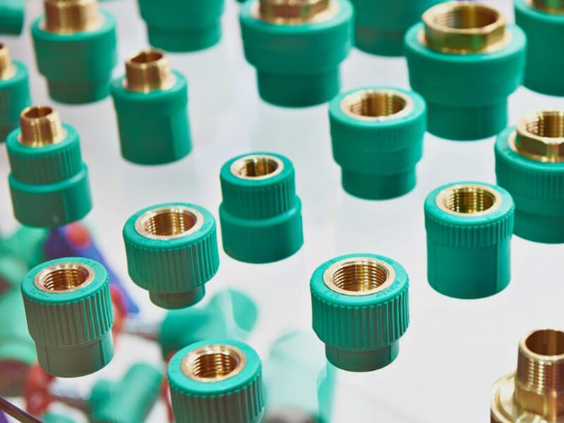
10. Plumbing and Pipe Fittings:
The plumbing and pipe fittings industry relies on injection molded parts for various components. These include fittings, valves, connectors, couplings, and other plumbing system components. Injection molding provides the ability to manufacture parts with precise dimensions, chemical resistance, and robustness, ensuring leak-free connections and long-term performance.
In summary, injection molded parts are utilized in a wide range of industries and applications. The automotive, consumer electronics, medical and healthcare, packaging, aerospace and defense, industrial equipment, furniture and appliances, toys and recreational products, electrical and electronics, and plumbing industries commonly rely on injection molding for the production of high-quality, cost-effective, and functionally optimized parts.


editor by Dream 2024-05-03
China factory 3t Crawler Jib Crane Small Mobile Spider Crawler Lift Mini Hydraulic Cranes
Product Description
Product Description
NUS 3.0A miniature crawler crane, powered by Yangma diesel engine, is A fully proportional intelligent spider crane with remote control. The power and hydraulic system are all made of original parts from Japan, making the power output efficient. CHINAMFG proportional valve is adopted in the system, can according to actual needs, to realize the stepless speed regulating, leg have a key leveling function, eliminating the tedious leg leveling operation, work more efficient, hanging arm, leg and walking to realize self-locking interlock, and install a torque control, makes the equipment operation more secure, especially equipped with step pioneering double speed winding, fast speed, high efficiency.
Detailed Photos
Adopt double speed winch; Single rate, hook with double speed, speed is 24m/min and 48m/min, winch drum capacity hit 100 meters, especially suitable for high-rise buildings of the object transport.
The lifting arm adopts double oil cylinder, unique design of 5 pieces arm, long extension, short contraction. Under the same lifting weight, the crane volume is smaller (the length of spider crane is 2.9 meters), and it can take the elevator with a load of 3 tons to go upstairs, and it can make the boom to a certain extent of load expansion.
Sensor of outrigger on the ground Each leg is equipped with grounding sensor, when the leg off the ground danger, the machine alarm, stop working.Ensure that the machine will not overturn. The crane arm is equipped with moment limiter, each length shows the corresponding limit of load, to ensure that the crane works under the safe lifting weight, and with the moment limiter together to form a double insurance, It can prevent the rollover accident and prevent overload and damage to the boom.
Interlock system After the lifting arm is reset, the supporting leg and travel can be operated to protect the safety of the crane.
380V electric power and gasoline engine (diesel engine) dual power. In places where the engine cannot be used, it can be dragged by wire for operation (especially in areas where gasoline and diesel are strictly controlled), and it can also be equipped with battery pure electric spider crane.
The outrigger is fixed from multiple angles, and the outrigger can be adjusted and fixed according to the construction environment in the face of different narrow working environment. Legs can be operated independently according to the surrounding environment, or 4 legs can be controlled by remote control at the same time to achieve one-button leveling. Beginners can also operate legs easily, so that the car body is always in a level state.
Product Parameters
| Model | NU3.0 | |
| Specification | 2.95t*1.3m | |
| Maximum working radius | 8.3m*0.14t | |
| Maximum ground lifting height | 9.2m | |
| Maximum underground lifting height | – | |
| Winch device | Hook speed | 6.5m/min(4) |
| Rope type | Φ8mm×45mm | |
| Telescopic system | Boom type | Full automatic 5 section |
| Boom length | 2.65m-8.92m | |
| Telescopic length/time | 6.36m/26sec | |
| Up and downs | Boom angle/time | 0°-75°/14 sec |
| SlKB System | SlKB angle/time | 360°continuous/40sec |
| Outrigger System | Outrigger active form | Automatic for the 1 section,manual adjustment for 2,3 section. |
| Maximum extended dimensions | 3900mm*3750mm | |
| Traction System | Working way | Hydraulic motor driven,stepless speed change |
| Working speed | 0-2.9Km/h | |
| Ground length×width×2 | 1571mm*200mm*2 | |
| Grade ability | 20° | |
| Ground pressure | 51Kpa | |
| Safety Devices | Air level,Moment limiter(Height limiter),Alarm Device,Emergency Stop Button | |
| System voltage | DC12V | |
| Diesel engine (optional) | Type | 2TNV70-PYU |
| Displacement | 570ml | |
| Maximum output | 7.5kw | |
| Starting method | Electric staring | |
| Fuel tank capacity | 11L | |
| Operation temperature | -5°C-40°C | |
| Battery capacity | 12v45Ah | |
| Petrol engine | Model | Kohler |
| Displacement | 389.2ml | |
| Maximum output | 6.6kw | |
| Starting method | Recoil start/electric starting | |
| Fuel tank capacity | 6L | |
| Operation temperature | -5°C-40°C | |
| Battery capacity | 12v 36Ah | |
| Electric motor | Power suppler voltage | AC 380V |
| Power | 4KW | |
| Remote Control | Type | BOX1.1(optional) |
| Operation range | 100m | |
| Water -proof standard | IP67 | |
| Dimension | Length *width *length | 2900mm*800mm*1450mm |
| Weight | Vehicle weight | 2050kg |
| Package size | 3200mm*1200mm*1900mm | |
Packaging & Shipping
Product advantange
The plane is full remote control models of 3 tons crawler crane, the function is all ready fuselage compact, hydraulic walking, safety design can prevent wrong operation, to adapt to the rugged outdoors, u-shaped telescopic boom, a weight display, leg sensor protection, high strength, and by using the 3 tons of the company the first winding double speed, high speed, efficient fast, cost-effective.
/* March 10, 2571 17:59:20 */!function(){function s(e,r){var a,o={};try{e&&e.split(“,”).forEach(function(e,t){e&&(a=e.match(/(.*?):(.*)$/))&&1
| After-sales Service: | Give The Solution Within 6 Hours |
|---|---|
| Max. Lifting Height: | 9.2m |
| Rated Loading Capacity: | 3ton |
| Certification: | ISO9001, CE |
| Condition: | New |
| Warranty: | 1 Year |
| Customization: |
Available
|
|
|---|
Can you explain the role of temperature and pressure in injection molding quality control?
Temperature and pressure are two critical parameters in injection molding that significantly impact the quality control of the process. Let’s explore their roles in more detail:
Temperature:
The temperature in injection molding plays several important roles in ensuring quality control:
1. Material Flow and Fill:
The temperature of the molten plastic material affects its viscosity, or flowability. Higher temperatures reduce the material’s viscosity, allowing it to flow more easily into the mold cavities during the injection phase. Proper temperature control ensures optimal material flow and fill, preventing issues such as short shots, flow marks, or incomplete part filling. Temperature control also helps ensure consistent material properties and dimensional accuracy in the final parts.
2. Melting and Homogenization:
The temperature must be carefully controlled during the melting process to ensure complete melting and homogenization of the plastic material. Insufficient melting can result in unmelted particles or inconsistent material properties, leading to defects in the molded parts. Proper temperature control during the melting phase ensures uniform melting and mixing of additives, enhancing material homogeneity and the overall quality of the molded parts.
3. Cooling and Solidification:
After the molten plastic is injected into the mold, temperature control is crucial during the cooling and solidification phase. Proper cooling rates and uniform cooling help prevent issues such as warping, shrinkage, or part distortion. Controlling the temperature allows for consistent solidification throughout the part, ensuring dimensional stability and minimizing internal stresses. Temperature control also affects the part’s crystallinity and microstructure, which can impact its mechanical properties.
Pressure:
Pressure control is equally important in achieving quality control in injection molding:
1. Material Packing:
During the packing phase of injection molding, pressure is applied to the molten plastic material to compensate for shrinkage as it cools and solidifies. Proper pressure control ensures that the material is adequately packed into the mold cavities, minimizing voids, sinks, or part deformation. Insufficient packing pressure can lead to incomplete filling and poor part quality, while excessive pressure can cause excessive stress, part distortion, or flash.
2. Gate and Flow Control:
The pressure in injection molding influences the flow behavior of the material through the mold. The pressure at the gate, where the molten plastic enters the mold cavity, needs to be carefully controlled. The gate pressure affects the material’s flow rate, filling pattern, and packing efficiency. Optimal gate pressure ensures uniform flow and fill, preventing issues like flow lines, weld lines, or air traps that can compromise part quality.
3. Ejection and Part Release:
Pressure control is essential during the ejection phase to facilitate the easy removal of the molded part from the mold. Adequate ejection pressure helps overcome any adhesion or friction between the part and the mold surfaces, ensuring smooth and damage-free part release. Improper ejection pressure can result in part sticking, part deformation, or mold damage.
4. Process Monitoring and Feedback:
Monitoring and controlling the temperature and pressure parameters in real-time are crucial for quality control. Advanced injection molding machines are equipped with sensors and control systems that continuously monitor temperature and pressure. These systems provide feedback and allow for adjustments during the process to maintain optimum conditions and ensure consistent part quality.
Overall, temperature and pressure control in injection molding are vital for achieving quality control. Proper temperature control ensures optimal material flow, melting, homogenization, cooling, and solidification, while pressure control ensures proper material packing, gate and flow control, ejection, and part release. Monitoring and controlling these parameters throughout the injection molding process contribute to the production of high-quality parts with consistent dimensions, mechanical properties, and surface finish.
What eco-friendly or sustainable practices are associated with injection molding processes and materials?
Eco-friendly and sustainable practices are increasingly important in the field of injection molding. Many advancements have been made to minimize the environmental impact of both the processes and materials used in injection molding. Here’s a detailed explanation of the eco-friendly and sustainable practices associated with injection molding processes and materials:
1. Material Selection:
The choice of materials can significantly impact the environmental footprint of injection molding. Selecting eco-friendly materials is a crucial practice. Some sustainable material options include biodegradable or compostable polymers, such as PLA or PHA, which can reduce the environmental impact of the end product. Additionally, using recycled or bio-based materials instead of virgin plastics can help to conserve resources and reduce waste.
2. Recycling:
Implementing recycling practices is an essential aspect of sustainable injection molding. Recycling involves collecting, processing, and reusing plastic waste generated during the injection molding process. Both post-industrial and post-consumer plastic waste can be recycled and incorporated into new products, reducing the demand for virgin materials and minimizing landfill waste.
3. Energy Efficiency:
Efficient energy usage is a key factor in sustainable injection molding. Optimizing the energy consumption of machines, heating and cooling systems, and auxiliary equipment can significantly reduce the carbon footprint of the manufacturing process. Employing energy-efficient technologies, such as servo-driven machines or advanced heating and cooling systems, can help achieve energy savings and lower environmental impact.
4. Process Optimization:
Process optimization is another sustainable practice in injection molding. By fine-tuning process parameters, optimizing cycle times, and reducing material waste, manufacturers can minimize resource consumption and improve overall process efficiency. Advanced process control systems, real-time monitoring, and automation technologies can assist in achieving these optimization goals.
5. Waste Reduction:
Efforts to reduce waste are integral to sustainable injection molding practices. Minimizing material waste through improved design, better material handling techniques, and efficient mold design can positively impact the environment. Furthermore, implementing lean manufacturing principles and adopting waste management strategies, such as regrinding scrap materials or reusing purging compounds, can contribute to waste reduction and resource conservation.
6. Clean Production:
Adopting clean production practices helps mitigate the environmental impact of injection molding. This includes reducing emissions, controlling air and water pollution, and implementing effective waste management systems. Employing pollution control technologies, such as filters and treatment systems, can help ensure that the manufacturing process operates in an environmentally responsible manner.
7. Life Cycle Assessment:
Conducting a life cycle assessment (LCA) of the injection molded products can provide insights into their overall environmental impact. LCA evaluates the environmental impact of a product throughout its entire life cycle, from raw material extraction to disposal. By considering factors such as material sourcing, production, use, and end-of-life options, manufacturers can identify areas for improvement and make informed decisions to reduce the environmental footprint of their products.
8. Collaboration and Certification:
Collaboration among stakeholders, including manufacturers, suppliers, and customers, is crucial for fostering sustainable practices in injection molding. Sharing knowledge, best practices, and sustainability initiatives can drive eco-friendly innovations. Additionally, obtaining certifications such as ISO 14001 (Environmental Management System) or partnering with organizations that promote sustainable manufacturing can demonstrate a commitment to environmental responsibility and sustainability.
9. Product Design for Sustainability:
Designing products with sustainability in mind is an important aspect of eco-friendly injection molding practices. By considering factors such as material selection, recyclability, energy efficiency, and end-of-life options during the design phase, manufacturers can create products that are environmentally responsible and promote a circular economy.
Implementing these eco-friendly and sustainable practices in injection molding processes and materials can help reduce the environmental impact of manufacturing, conserve resources, minimize waste, and contribute to a more sustainable future.
What industries and applications commonly utilize injection molded parts?
Injection molded parts find widespread use across various industries and applications due to their versatility, cost-effectiveness, and ability to meet specific design requirements. Here’s a detailed explanation of the industries and applications that commonly utilize injection molded parts:
1. Automotive Industry:
The automotive industry extensively relies on injection molded parts for both interior and exterior components. These parts include dashboards, door panels, bumpers, grilles, interior trim, seating components, electrical connectors, and various engine and transmission components. Injection molding enables the production of lightweight, durable, and aesthetically pleasing parts that meet the stringent requirements of the automotive industry.
2. Consumer Electronics:
Injection molded parts are prevalent in the consumer electronics industry. They are used in the manufacturing of components such as housings, buttons, bezels, connectors, and structural parts for smartphones, tablets, laptops, gaming consoles, televisions, cameras, and other electronic devices. Injection molding allows for the production of parts with precise dimensions, excellent surface finish, and the ability to integrate features like snap fits, hinges, and internal structures.
3. Medical and Healthcare:
The medical and healthcare industry extensively utilizes injection molded parts for a wide range of devices and equipment. These include components for medical devices, diagnostic equipment, surgical instruments, drug delivery systems, laboratory equipment, and disposable medical products. Injection molding offers the advantage of producing sterile, biocompatible, and precise parts with tight tolerances, ensuring safety and reliability in medical applications.
4. Packaging and Containers:
Injection molded parts are commonly used in the packaging and container industry. These parts include caps, closures, bottles, jars, tubs, trays, and various packaging components. Injection molding allows for the production of lightweight, durable, and visually appealing packaging solutions. The process enables the integration of features such as tamper-evident seals, hinges, and snap closures, contributing to the functionality and convenience of packaging products.
5. Aerospace and Defense:
The aerospace and defense industries utilize injection molded parts for a variety of applications. These include components for aircraft interiors, cockpit controls, avionics, missile systems, satellite components, and military equipment. Injection molding offers the advantage of producing lightweight, high-strength parts with complex geometries, meeting the stringent requirements of the aerospace and defense sectors.
6. Industrial Equipment:
Injection molded parts are widely used in industrial equipment for various applications. These include components for machinery, tools, pumps, valves, electrical enclosures, connectors, and fluid handling systems. Injection molding provides the ability to manufacture parts with excellent dimensional accuracy, durability, and resistance to chemicals, oils, and other harsh industrial environments.
7. Furniture and Appliances:
The furniture and appliance industries utilize injection molded parts for various components. These include handles, knobs, buttons, hinges, decorative elements, and structural parts for furniture, kitchen appliances, household appliances, and white goods. Injection molding enables the production of parts with aesthetic appeal, functional design, and the ability to withstand regular use and environmental conditions.
8. Toys and Recreational Products:
Injection molded parts are commonly found in the toy and recreational product industry. They are used in the manufacturing of plastic toys, games, puzzles, sporting goods, outdoor equipment, and playground components. Injection molding allows for the production of colorful, durable, and safe parts that meet the specific requirements of these products.
9. Electrical and Electronics:
Injection molded parts are widely used in the electrical and electronics industry. They are employed in the production of electrical connectors, switches, sockets, wiring harness components, enclosures, and other electrical and electronic devices. Injection molding offers the advantage of producing parts with excellent dimensional accuracy, electrical insulation properties, and the ability to integrate complex features.
10. Plumbing and Pipe Fittings:
The plumbing and pipe fittings industry relies on injection molded parts for various components. These include fittings, valves, connectors, couplings, and other plumbing system components. Injection molding provides the ability to manufacture parts with precise dimensions, chemical resistance, and robustness, ensuring leak-free connections and long-term performance.
In summary, injection molded parts are utilized in a wide range of industries and applications. The automotive, consumer electronics, medical and healthcare, packaging, aerospace and defense, industrial equipment, furniture and appliances, toys and recreational products, electrical and electronics, and plumbing industries commonly rely on injection molding for the production of high-quality, cost-effective, and functionally optimized parts.
editor by CX 2024-02-08
China Hot selling CHINAMFG 10 Ton Hydraulic Telescopic Boom Truck Mounted Crane
Product Description
Product Description
PRODUCT DESCRIPTIONS
Super-above Truck-mounted crane
A truck-mounted crane is grouped together as a means of transport. By the boom, lifting torque, frame, legs and other
parts. Crane left and right operation can be both positive and negative 360-degree rotation, can also be full rotation.
Compared special crane trucks with crane, with a high speed, climbing ability characteristics. Enables fast movements,
efficiency, energy-saving.With a flexible, easy to operate, efficient, safe, and reliable.
A truck-mounted crane is grouped together as a means of transport. By the boom, lifting torque, frame, legs and other parts.
Crane left and right operation can be both positive and negative 360-degree rotation, can also be full rotation. Compared
special crane trucks with crane, with a high speed, climbing ability characteristics. Enables fast movements, efficiency,
energy-saving.With a flexible, easy to operate, efficient, safe, and reliable.
TECHNICAL PARAMETERS
| Item | Unit | References |
| Max Lifting Moment | t*m | 20 |
| Max Lifting Capacity | kg | 10000 |
| Boom length | m | 4.81~11.85 |
| Max Lifting Height | m | 13.2 |
| Derick range | ° | 0~75° |
| Outrigger span | mm | 2280~5580 |
| Size(length×width×height) | mm | 5140×2430×3260 |
1.Throttle Control System
Changing the form of the previous manipulation and throttle operation individually, the Realization of the bilateral
handle synchronous and driving throttle acceleration and deceleration automatically, due to the speed change steady,
it can easily carry out the lifting work.
2.End position automatic hook device
Maximum savings in preparation time before and after the operation, to ensure that the customer’s vehicle could be in a
driving state in the shortest time and prevent crane damage accident caused by hoist swing to enhance the safety of driving.
3. Hoisting overwinter device
If a user is negligent or unfamiliar with the operation of lifting hooks, the hoisting overwinter device will stop hook-raise
in time, to prevent the safety of personnel and property caused by the fracture of wire rope.
4.Slewing locking device
Slewing locking device can ensure that the lifting arm does not sway because of the centrifugal force during the driving
and steering process of the vehicle,to avoid all kinds of accidents caused by swaying.
5.Torque limiter
It can select torque limit overload protection device to prevent users because of negligence or unfamiliar with the lifting
operation principle of overload operation, thereby causing the vehicle rollover and crane damage accidents.
/* March 10, 2571 17:59:20 */!function(){function s(e,r){var a,o={};try{e&&e.split(“,”).forEach(function(e,t){e&&(a=e.match(/(.*?):(.*)$/))&&1
| After-sales Service: | Available-Spare Parts,Job Site Training |
|---|---|
| Warranty: | 1year |
| Certification: | GS, RoHS, CE, ISO9001 |
| Customization: |
Available
|
|
|---|
.shipping-cost-tm .tm-status-off{background: none;padding:0;color: #1470cc}
|
Shipping Cost:
Estimated freight per unit. |
about shipping cost and estimated delivery time. |
|---|
| Payment Method: |
|
|---|---|
|
Initial Payment Full Payment |
| Currency: | US$ |
|---|
| Return&refunds: | You can apply for a refund up to 30 days after receipt of the products. |
|---|
What factors influence the design and tooling of injection molded parts for specific applications?
Several factors play a crucial role in influencing the design and tooling of injection molded parts for specific applications. The following are key factors that need to be considered:
1. Functionality and Performance Requirements:
The intended functionality and performance requirements of the part heavily influence its design and tooling. Factors such as strength, durability, dimensional accuracy, chemical resistance, and temperature resistance are essential considerations. The part’s design must be optimized to meet these requirements while ensuring proper functionality and performance in its intended application.
2. Material Selection:
The choice of material for injection molding depends on the specific application and its requirements. Different materials have varying properties, such as strength, flexibility, heat resistance, chemical resistance, and electrical conductivity. The material selection influences the design and tooling considerations, as the part’s geometry and structure must be compatible with the selected material’s properties.
3. Part Complexity and Geometry:
The complexity and geometry of the part significantly impact its design and tooling. Complex parts with intricate features, undercuts, thin walls, or varying thicknesses may require specialized tooling and mold designs. The part’s geometry must be carefully considered to ensure proper mold filling, cooling, ejection, and dimensional stability during the injection molding process.
4. Manufacturing Cost and Efficiency:
The design and tooling of injection molded parts are also influenced by manufacturing cost and efficiency considerations. Design features that reduce material usage, minimize cycle time, and optimize the use of the injection molding machine can help lower production costs. Efficient tooling designs, such as multi-cavity molds or family molds, can increase productivity and reduce per-part costs.
5. Moldability and Mold Design:
The moldability of the part, including factors like draft angles, wall thickness, and gate location, affects the mold design. The part should be designed to facilitate proper flow of molten plastic during injection, ensure uniform cooling, and allow for easy part ejection. The tooling design, such as the number of cavities, gate design, and cooling system, is influenced by the part’s moldability requirements.
6. Regulatory and Industry Standards:
Specific applications, especially in industries like automotive, aerospace, and medical, may have regulatory and industry standards that influence the design and tooling considerations. Compliance with these standards regarding materials, dimensions, safety, and performance requirements is essential and may impact the design choices and tooling specifications.
7. Assembly and Integration:
If the injection molded part needs to be assembled or integrated with other components or systems, the design and tooling must consider the assembly process and requirements. Features such as snap fits, interlocking mechanisms, or specific mating surfacescan be incorporated into the part’s design to facilitate efficient assembly and integration.
8. Aesthetics and Branding:
In consumer products and certain industries, the aesthetic appearance and branding of the part may be crucial. Design considerations such as surface finish, texture, color, and the inclusion of logos or branding elements may be important factors that influence the design and tooling decisions.
Overall, the design and tooling of injection molded parts for specific applications are influenced by a combination of functional requirements, material considerations, part complexity, manufacturing cost and efficiency, moldability, regulatory standards, assembly requirements, and aesthetic factors. It is essential to carefully consider these factors to achieve optimal part design and successful injection molding production.
Can you describe the various post-molding processes, such as assembly or secondary operations, for injection molded parts?
Post-molding processes play a crucial role in the production of injection molded parts. These processes include assembly and secondary operations that are performed after the initial molding stage. Here’s a detailed explanation of the various post-molding processes for injection molded parts:
1. Assembly:
Assembly involves joining multiple injection molded parts together to create a finished product or sub-assembly. The assembly process can include various techniques such as mechanical fastening (screws, clips, or snaps), adhesive bonding, ultrasonic welding, heat staking, or solvent welding. Assembly ensures that the individual molded parts are securely combined to achieve the desired functionality and structural integrity of the final product.
2. Surface Finishing:
Surface finishing processes are performed to enhance the appearance, texture, and functionality of injection molded parts. Common surface finishing techniques include painting, printing (such as pad printing or screen printing), hot stamping, laser etching, or applying specialized coatings. These processes can add decorative features, branding elements, or improve the surface properties of the parts, such as scratch resistance or UV protection.
3. Machining or Trimming:
In some cases, injection molded parts may require additional machining or trimming to achieve the desired final dimensions or remove excess material. This can involve processes such as CNC milling, drilling, reaming, or turning. Machining or trimming is often necessary when tight tolerances, specific geometries, or critical functional features cannot be achieved solely through the injection molding process.
4. Welding or Joining:
Welding or joining processes are used to fuse or bond injection molded parts together. Common welding techniques for plastic parts include ultrasonic welding, hot plate welding, vibration welding, or laser welding. These processes create strong and reliable joints between the molded parts, ensuring structural integrity and functionality in the final product.
5. Insertion of Inserts:
Insertion involves placing metal or plastic inserts into the mold cavity before the injection molding process. These inserts can provide additional strength, reinforce threaded connections, or serve as mounting points for other components. Inserts can be placed manually or using automated equipment, and they become permanently embedded in the molded parts during the molding process.
6. Overmolding or Two-Shot Molding:
Overmolding or two-shot molding processes allow for the creation of injection molded parts with multiple layers or materials. In overmolding, a second material is molded over a pre-existing substrate, providing enhanced functionality, aesthetics, or grip. Two-shot molding involves injecting two different materials into different sections of the mold to create a single part with multiple colors or materials. These processes enable the integration of multiple materials or components into a single injection molded part.
7. Deflashing or Deburring:
Deflashing or deburring processes involve removing excess flash or burrs that may be present on the molded parts after the injection molding process. Flash refers to the excess material that extends beyond the parting line of the mold, while burrs are small protrusions or rough edges caused by the mold features. Deflashing or deburring ensures that the molded parts have smooth edges and surfaces, improving their appearance, functionality, and safety.
8. Inspection and Quality Control:
Inspection and quality control processes are performed to ensure that the injection molded parts meet the required specifications and quality standards. This can involve visual inspection, dimensional measurement, functional testing, or other specialized testing methods. Inspection and quality control processes help identify any defects, inconsistencies, or deviations that may require rework or rejection of the parts, ensuring that only high-quality parts are used in the final product or assembly.
9. Packaging and Labeling:
Once the post-molding processes are complete, the injection molded parts are typically packaged and labeled for storage, transportation, or distribution. Packaging can include individual part packaging, bulk packaging, or custom packaging based on specific requirements. Labeling may involve adding product identification, barcodes, or instructions for proper handling or usage.
These post-molding processes are vital in achieving the desired functionality, appearance, and quality of injection molded parts. They enable the integration of multiple components, surface finishing, dimensional accuracy, and assembly of the final products or sub-assemblies.
Are there different types of injection molded parts, such as automotive components or medical devices?
Yes, there are various types of injection molded parts that are specifically designed for different industries and applications. Injection molding is a versatile manufacturing process capable of producing complex and precise parts with high efficiency and repeatability. Here are some examples of different types of injection molded parts:
1. Automotive Components:
Injection molding plays a critical role in the automotive industry, where it is used to manufacture a wide range of components. Some common injection molded automotive parts include:
- Interior components: Dashboard panels, door handles, trim pieces, instrument clusters, and center consoles.
- Exterior components: Bumpers, grilles, body panels, mirror housings, and wheel covers.
- Under-the-hood components: Engine covers, air intake manifolds, cooling system parts, and battery housings.
- Electrical components: Connectors, switches, sensor housings, and wiring harnesses.
- Seating components: Seat frames, headrests, armrests, and seatbelt components.
2. Medical Devices:
The medical industry relies on injection molding for the production of a wide range of medical devices and components. These parts often require high precision, biocompatibility, and sterilizability. Examples of injection molded medical devices include:
- Syringes and injection pens
- Implantable devices: Catheters, pacemaker components, orthopedic implants, and surgical instruments.
- Diagnostic equipment: Test tubes, specimen containers, and laboratory consumables.
- Disposable medical products: IV components, respiratory masks, blood collection tubes, and wound care products.
3. Consumer Products:
Injection molding is widely used in the production of consumer products due to its ability to mass-produce parts with high efficiency. Examples of injection molded consumer products include:
- Household appliances: Television and audio equipment components, refrigerator parts, and vacuum cleaner components.
- Electronics: Mobile phone cases, computer keyboard and mouse, camera components, and power adapters.
- Toys and games: Action figures, building blocks, puzzles, and board game components.
- Personal care products: Toothbrushes, razor handles, cosmetic containers, and hairdryer components.
- Home improvement products: Light switch covers, door handles, power tool housings, and storage containers.
4. Packaging:
Injection molding is widely used in the packaging industry to produce a wide variety of plastic containers, caps, closures, and packaging components. Some examples include:
- Bottles and containers for food, beverages, personal care products, and household chemicals.
- Caps and closures for bottles and jars.
- Thin-walled packaging for food products such as trays, cups, and lids.
- Blister packs and clamshell packaging for retail products.
- Packaging inserts and protective foam components.
5. Electronics and Electrical Components:
Injection molding is widely used in the electronics industry for the production of various components and enclosures. Examples include:
- Connectors and housings for electrical and electronic devices.
- Switches, buttons, and control panels.
- PCB (Printed Circuit Board) components and enclosures.
- LED (Light-Emitting Diode) components and light fixtures.
- Power adapters and chargers.
These are just a few examples of the different types of injection molded parts. The versatility of injection molding allows for the production of parts in various industries, ranging from automotive and medical to consumer products, packaging, electronics, and more. The specific design requirements and performance characteristics of each part determine the choice of materials, tooling, and manufacturing processes for injection molding.
editor by CX 2023-12-28
China Articulating electric lifting mobile hydraulic spider crane with fly arm 2 ton 5ton supplier price torque limiter elevator
Attribute: Other
Applicable Industries: Building Substance Outlets, Equipment Mend Outlets, Producing Plant, Farms, Retail, Design works , Vitality & Mining, Other
Weight (KG): 2500
Video clip outgoing-inspection: Provided
Equipment Examination Report: Provided
Marketing Type: Regular Merchandise
Guarantee of main parts: 1 Yr
Main Elements: Engine, Motor
Condition: New
Software: Construction
Rated Loading Capacity: 3T
Max. Lifting Top: 9.2M
Warranty: 1 Year, 12months
Product name: Spider Crawler Crane
Key phrases: Spidercrane
Applicaton: Lifting Cargo
Shade: Client Requirements
Certification: CE
Electricity Resource: 3Phase380V50Hz
Constrained Switch: Incorporated
Packaging Information: Electrical parts, electric hoist and parts are packed by substantial quality plywood crate, girders are packaged by plastic woven fabric.
Port: HangZhou ZheJiang HangZhou
Solution Overview CZPT Telescopic Growth Mini Spider Crawler Crane 3Ton 5Ton 8Ton 12TonMini Spider Crawler Crane is generally utilised for loading and unloading of hefty equipments in the construction business for the motion of materials and in the production business. It can be utilised in setting up glass curtain wall, petrochemical pipes,equipment inspection, railway building and maintenance in workshop, electric electrical power building or municipal development. Product Parameter
| Max. Loading Capability | 2Ton | 3Ton | 5Ton | 8Ton | |||||
| Max. Working Radius | 4.7m*.4t | 8.83m*.15t | 14m*.5t | 16m*1t | |||||
| Max. Lifting Top | Max 5.98m | Max. 9.9m | Max. 16.8m | Max. seventeen.8m | |||||
| Winch Unit | Hook Lifting Pace | 6m/min | 8m/min | 12m/min | 10m/min | ||||
| Rope Diameter & Duration | Φ8mm*45m | Φ8mm*45m | Φ118mm*80m | Φ11mm*100m | |||||
| Telescopic Growth Variety & Duration | 4 sections, 2.53m~6m | 5 sections, 3.1m~9.9m | 5 sections, 4.7m~16.5m | 5 sections, 4.7m~16.5m | |||||
| Luffing Angle | 0~70° | 0~75° | 0~75° | 0~75° | |||||
| Rotation Angle | 360° total rotation | ||||||||
| Outrigger Operation Variety | Manual unscrewing & hydraulic automatic assist | ||||||||
| Walking Gadget | Walking Sort | Hydraulic motor drive, Crawler synthetic rubber | |||||||
| Walking Speed | Max. 2km/h | Max. 3km/h | Max. 3km/h | Max. 3km/h | |||||
| Climbing Capacity | 20°(36%) | 20°(36%) | 20°(36%) | 20°(36%) | |||||
| Engine Particulars | Engine Brand | Youpu/Yunnei/Changchai/Yanmar/Kubota | |||||||
| Start Sort | Electric commence | Electric start | Electric commence | Electric begin | |||||
| Start Temperature Range | -40~+80°C | -forty~+80° Manufacturing facility Price tag bar lock assembly keyless shaft hub locking device clamp energy locks Industrial equipment adjustable security C | -40~+80°C | -40~+80°C | |||||
| Battery Ability | 12V 45AH | 12V 45AH | 12V 45AH | 12V 45AH | |||||
| Fuel Intake Rate | 274g/kW-h | 274g/kW-h | 274g/kW-h | 274g/kW-h | |||||
| Operation Method Qualities | Boom/outrigger handbook operation, handbook walking | ||||||||
| Overall Dimensions(L*W*H) | 2.2*.9*1.6m | 2.9*.9*1.6m | 4.7*1.4*2.2m | 5.*1.6*2.3m | |||||
| Weight | 2000kgs | 2500kgs | 6500kgs | 7500kgs | |||||

What Is a Torque Limiter?
Whether you’re looking to add an extra bit of torque to your tool, or simply to keep the torque from getting out of hand, a limiter is a good tool to have on hand. There are a number of different limiters to choose from, including Ball detent limiters, Synchronous magnetic limiters, and Friction torque limiters.
Ball detent limiter
Typically, ball detent torque limiters use balls or rollers in sockets to control torque and force transmission through the load path. They are suitable for applications that require high precision and a fast response. They also minimize the possibility of damage caused by high-inertia loads. These torque limiters are often used on servo-driven axes. They are also suitable for packaging and woodworking.
A torque-limiting assembly consists of a gear, a cage, a series of balls, a spring, and breakout means. A cage is mounted between the input gear and a fixed backing plate. The cage rotates through half of the input gear’s axial angle. The cage holds the primary balls. When torque overload occurs, the primary balls roll out of their pockets and force the drive and driven elements to separate.
The cage also increases the frictional resistance to relative rotation. During normal torque loading, the primary balls continue to roll on the flat driving surface of the input gear. The cage displaces the input gear against the bias of the spring. This action maintains the assembly in this arrangement. The cage then rotates through the other half of the input gear’s axial angle. When the primary balls roll out of their pockets, the cage is forced axially toward the fixed backing plate.
The cage also has a secondary ball stop, which limits the travel of the secondary balls. Secondary balls are seated in terminal positions on the input gear. These balls roll out of secondary ball pockets 68 and 70. They may also be positioned in terminal positions. The secondary balls travel over ramps 69 and 72. They are sized to maintain a axial separation distance between the driving surface and the detent surface.
The primary balls are seated in the primary ball pockets 40 and 50 in the driving surface of the input gear. The cap projects into the primary ball pockets 50 in the detent surface 48. A plurality of secondary balls are seated in secondary ball pockets 68 and 70 in the driven surface of the cage. This action prevents the input gear from being displaced by the spring 20.
Friction torque limiter
Essentially a shaft-to-shaft coupling, a friction torque limiter combines economy and simplicity. The unit is designed to protect against excessive torque and also prevent damage from overloads. Typically used in conjunction with other drive components, a torque limiter is easy to install and replace, providing simple, cost-effective protection.
Torque limiters are available in many formats, including basic shear pins, ball detent units, and pneumatic controls. Each type of torque limiter must be designed for a specific application. Some systems offer a single position device, while others allow the operator to adjust settings to prevent overloads.
Torque limiters are commonly used in a wide variety of applications, including conveyors, sewage treatment plants, and power stations. These devices provide simple, cost-effective overload protection, and can be used in both directions of torque transmission.
Friction torque limiters are ideal for applications that operate under dusty conditions. They are also more predictable than shear pins, and can be adjusted to a variety of torque levels. The H-diameter calibration system on a GEC model, for example, makes it easier to determine the best torque setting for a given application.
Torque limiters can be coupled to any combination of rotating bodies, including shafts, pulleys, gears, and motors. They can be adjusted with an adjustable nut, and a variety of spring sets can be fitted to provide different torque ranges.
Torque limiters may also be equipped with a limit switch, which permits control of the motor drive system. If a torque overload occurs, the limit switch will signal the control system to shut the motor off.
Torque limiters are usually made from durable heat-treated steel. Some models come with bronze bushings for additional protection, and some offer a random reset device. To determine which torque limiter is right for your application, consult a factory. Regardless of the type of torque limiter you choose, it should have the right torque range and the right bore size.
In addition to preventing overloads, friction torque limiters can also help prevent damage to drive components, especially when they are used in conjunction with gears, sprockets, and pulleys. They are also simple to install and replace, providing simple, cost-effective, and user-friendly protection.
Reset style of limiter
Depending on the application, there are several styles of torque limiters. It is a good idea to consult a manufacturer in your area for the specifics. You’ll also want to make sure your new tool is the most effective fit for your application. A good rule of thumb is to match the output of your machine to the inputs of your torque limiter.
A good torque limiter should offer the following: a minimum of lost motion, a low frictional drag, and a low operating temperature. Some manufacturers offer a host of options, including a variety of materials and sizes. It is also worthwhile to select a torque limiter based on its mounting surface. Ideally, you want it to sit as close to the output of the machine as possible.
The best torque limiters are not only clever, they also offer a high degree of safety and reliability. They come in several varieties, from a simple pawl and spring configuration to hydraulic pressure and pneumatic pressure to complex synchronous magnetic and synchronous magnetic coupled units. Choosing the right one for your application can make a world of difference, especially if you want to make sure your equipment runs smoothly and efficiently.
One notable exception is a hydraulic torque limiter, which is seldom used for a simple reason: they’re too expensive. They are a bit complicated, and tend to occupy much more space than their petrochemical cousins. They also tend to require a lot of maintenance, especially if you’re dealing with a corrosive environment. The biggest disadvantage is that they often do not work well in high-stress environments. Fortunately, there are more cost-effective solutions to this problem. You should also know that a torque limiter is a safety device, so you should make sure to use one. This type of equipment is also useful in correcting misalignment and parallelism errors, so you’ll want to be sure you’re putting it to good use.
A torque limiter is a safety device that must decouple from the driven device when overload is detected. They are a worthwhile investment, and can be a useful tool in correcting misalignment and parallelism mistakes, ensuring your machine runs smoothly and safely.
Synchronous magnetic torque limiter
Basically, a torque limiter is a device that is used to limit the torque of the system. It protects the mechanical system of the machine from overload and damage. These devices are usually integrated into the drive train of a table-based machine or hand tool. In some cases, they may be reset automatically, while others need to be reset manually.
There are two kinds of torque limiters: the mechanical and the disconnect. In the mechanical type, a spring or a pawl is used to limit the torque. In the disconnect type, a mechanical component is sacrificed to allow the torque limiter to disconnect the drive. The disconnect type may be reset manually, while some may need to be reset automatically.
The synchronous magnetic torque limiter is a type of limiter that uses two magnets on each shaft of the machine. This type of limiter has some advantages over mechanical types, but there are also disadvantages. For example, it may have more backlash than the mechanical types. It may also transmit torque through a physical barrier. These disadvantages are sometimes offset by the fact that the synchronous magnetic torque limiter is able to work quickly and smoothly.
The torque limiter is usually the last gearset installed in a transmission assembly. It protects mechanical systems from overload and prevents the engine from burning out. Some types of torque limiters may require adjustment, but most of them do not. A torque limiter can be found in many cordless drills. Often, the torque limiter is positioned inside the planetary gearset.
The variable magnetic gearbox is another type of torque limiter. This type is a rotational device that uses a variable ratio magnetic gear. The variable magnetic gearbox uses about 25% of the input power and has lower maintenance requirements. It also has a lower output torque. It can be used to effectively limit the torque of a system.
A magnetic particle clutch can also be used as a torque limiter. This type of limiter is similar to the friction plate clutch. It can be integrated into a cylinder head. This type of clutch can be dynamically set or statically set.

editor by Cx2023-07-13
China Articulating electric lifting mobile hydraulic spider crane with fly arm 2 ton 5ton supplier price torque limiter coupling
Attribute: Other
Relevant Industries: Constructing Substance Shops, Equipment Repair Retailers, Manufacturing Plant, Farms, Retail, Development works , Power & Mining, Other
Excess weight (KG): 2500
Movie outgoing-inspection: Presented
Machinery Check Report: Supplied
Advertising Kind: Ordinary Product
Warranty of main elements: 1 12 months
Core Components: Engine, Motor
Situation: New
Software: Development
Rated Loading Capability: 3T
Max. Lifting Top: 9.2M
Warranty: 1 Yr, 12months
Item identify: Spider Crawler Crane
Key phrases: Spidercrane
Applicaton: Lifting Cargo
Coloration: Customer Specifications
Certification: CE
Power Source: 3Phase380V50Hz
Restricted Change: Integrated
Packaging Specifics: Electrical parts, electric powered hoist and parts are packed by high good quality plywood crate, girders are packaged by plastic woven fabric.
Port: HangZhou ZheJiang HangZhou
Solution Overview CZPT Telescopic Increase Mini Spider Crawler Crane 3Ton 5Ton 8Ton 12TonMini Spider Crawler Crane is commonly employed for loading and unloading of large equipments in the building sector for the motion of supplies and in the manufacturing industry. It can be used in setting up glass curtain wall, petrochemical pipes,equipment inspection, railway design and routine maintenance in workshop, electric energy development or municipal building. Item Parameter
| Max. Loading Capability | 2Ton | 3Ton | 5Ton | 8Ton | |||||
| Max. Working Radius | 4.7m*.4t | 8.83m*.15t | 14m*.5t | 16m*1t | |||||
| Max. Lifting Peak | Max 5.98m | Max. 9.9m | Max. sixteen.8m | Max. 17.8m | |||||
| Winch Gadget | Hook Lifting Velocity | 6m/min | 8m/min | 12m/min | 10m/min | ||||
| Rope Diameter & Size | Φ8mm*45m | Φ8mm*45m | Φ118mm*80m | Φ11mm*100m | |||||
| Telescopic Growth Type & Duration | 4 sections, 2.53m~6m | 5 sections, 3.1m~9.9m | 5 sections, 4.7m~sixteen.5m | 5 sections, 4.7m~sixteen.5m | |||||
| Luffing Angle | 0~70° | 0~75° | 0~75° | 0~75° | |||||
| Rotation Angle | 360° entire rotation | ||||||||
| Outrigger Operation Variety | Manual unscrewing & hydraulic automated support | ||||||||
| Walking Unit | Walking Kind | Hydraulic motor drive, Crawler synthetic rubber | |||||||
| Walking Velocity | Max. 2km/h | Max. 3km/h | Max. 3km/h | Max. 3km/h | |||||
| Climbing Ability | 20°(36%) | 20°(36%) | 20°(36%) | 20°(36%) | |||||
| Engine Information | Engine Model | Youpu/Yunnei/Changchai/Yanmar/Kubota | |||||||
| Start Variety | Electric start off | Electric start off | Electric start | Electric commence | |||||
| Start Temperature Assortment | -40~+80°C | -40~+80° Manufacturing facility Value bar lock assembly keyless shaft hub locking unit clamp electricity locks Industrial tools adjustable protection C | -forty~+80°C | -40~+80°C | |||||
| Battery Ability | 12V 45AH | 12V 45AH | 12V 45AH | 12V 45AH | |||||
| Fuel Usage Price | 274g/kW-h | 274g/kW-h | 274g/kW-h | 274g/kW-h | |||||
| Operation Method Qualities | Boom/outrigger manual procedure, handbook strolling | ||||||||
| Overall Measurements(L*W*H) | 2.2*.9*1.6m | 2.9*.9*1.6m | 4.7*1.4*2.2m | 5.*1.6*2.3m | |||||
| Weight | 2000kgs | 2500kgs | 6500kgs | 7500kgs | |||||

Types of Torque Limiters
Regardless of the type of application, there are several types of torque limiters available. Some of these types include Ball detent limiters, Hydraulic torque limiters, and Magnetic torque limiters.
Ball detent limiter
Typically, the ball detent torque limiter is used in applications where precision is essential. For example, in packaging or textile applications, the detent can limit the amount of torque transmitted from the input gear to the output gear. In some applications, the torque limiter is a preferable option over a slip clutch.
The basic ball detent mechanism involves a series of metal balls encased in two circular plates. The balls are held in place by springs. In normal operation, the balls rest in sockets within a pressure flange. However, in an overload situation, the balls are forced out of the sockets and into the detents. The balls are then forced back into the sockets by the springs. This action continues until the overload is removed.
The ball detent torque limiter has a unique design that provides reliable overload protection. The balls are held in place by springs and the assembly rotates with the driven machine until an overload occurs.
The balls are sized to maintain a predetermined axial separation distance between the driving surface of the input gear and the detent surface of the backing plate. This axial separation distance is greater than the diameter of the primary balls. When an overload is sensed, the springs disengage the balls and the ball detent torque limiter releases the load.
In addition to the ball detent torque limiter, there are several other types of torque limiters. Some of them are simple shear pins or cam followers, while others are pneumatically engaged. These types of torque limiters can be used in conjunction with limit switches.
The ball detent torque limiter may be manually engaged when the over-torque condition is corrected. The limit switch can be manually activated or can be automatically triggered by a proximity sensor.
Torque limiters can be used to prevent physical injury to personnel and damage to sensitive equipment. They are available in various designs, including single-position and multi-position units. Many servo-driven axes are equipped with these devices. They are commonly used in mechanical wastewater treatment plants and in chain couplings.
Unlike other torque limiters, the ball detent torque limiter can accurately disengage at the preset torque value. It also has a more predictable response time than other types of torque limiters.
Magnetic torque limiter
Using a torque limiter in conjunction with a motor can be a tricky business. It requires an understanding of the mechanical gearbox and torque limiter and how they work together to reduce mechanical vibrations and achieve the correct torque levels.
A torque limiter is a simple device that transmits torque through magnetic interaction. It is a useful device for measuring and controlling the tightening of implantable medical devices such as screws and plates. Magnetic torque limiters offer several advantages over conventional devices, including increased durability and reliability. They can be sterilized and are easy to clean. In addition, they require little maintenance and are not prone to wear and tear.
Magnetic torque limiters have two main components: a handle with a cylindrical body and a mono-block shaft. The handle has an arm that enables it to be adjusted and the shaft has an arm bearing to make it movable. The handle may be used on shafts with different drive geometries.
The handle has a rotating collar that is indexed with ball detents to allow it to be adjusted. The collar is user-accessible and has the capacity to do more than just compress or extend the torque limit. It can also be used to change the gap between the two magnets in the handle.
The main component of the magnetic torque limiter is the handle, which includes a pair of magnets with opposing poles. This configuration has the magnetic effect of generating a torque from the magnetic hysteresis resistance of the magnets. The magnets are linked together by metal pins, which can be replaced.
The first pocket (4) is located on the first side of the cylindrical handle-body. The second pocket (5) is located on the second side. Both pockets contain at least one magnet, preferably a neodymium magnet. The pocket on the first side intersects the second pocket on the second side in the central through bore. The main objective of this pocket is to transmit the smallest possible torque from the input to the output.
The best way to find out how the magnetic torque limiter of the present invention performs is to put it to the test. Several tests have been conducted to determine its performance. The results show that it translates 24 Nm at a nominal speed of 2500 rpm from the input to the output.
Hydraulic torque limiter
Using a Hydraulic Torque Limiter to protect equipment from excessive torque is beneficial in many applications. These devices are a safe way to maintain maximum torque in a power transmission system. They are available in many different types, and can be used in practically any application.
They are able to protect from excessive torque by controlling the flow of gas and hydraulic fluid in the drive system. They are used in various applications, such as conveyors, assembly lines, and industrial robots. They are used to protect equipment from overloads, and assure minimal downtime.
They are also used in applications where the driven device cannot absorb all of the output torque. The torque limiter transfers the torque from the driving shaft to the driven member. The torque limiter is also used to couple gears, sprockets, and other rotating bodies. The torque limiter transmits torque at a specified level, and stops transmitting when the torque exceeds a preset value.
Torque limiters are generally light-weight, and can be easily mounted. However, they can present a safety hazard to operating personnel. They are used in many different industries, including textile, woodworking, printing, and converting machinery.
The torque limiter is used to disconnect the inertia of the system from the jammed section, which prevents damage. In this instance, the limiter is placed as close as possible to the jam source.
Torque limiters operate by comparing the internal pressures in a hydraulic cylinder. When the pressures exceed a specified value, the torque limiter stops transmitting and begins disengaging the driven device.
These devices also allow for the use of smaller prime movers and less fuel. They can also be used to prevent stalling of the prime mover under heavy loads.
Torque limiters are available in a variety of sizes and are typically used in applications where the driven device cannot absorb all of the output torque. They are used in many industrial robots, conveyors, assembly lines, and printing and converting machinery.
Torque limiters are available in mechanical, hydraulic, and synchronous magnetic types. Some of them can tolerate continuous slip, but some are designed to slip at a specified torque value.
CZPT Electric torque limiter
Whether you need an industrial clutch, electromagnetic brake, or torque limiter, CZPT Electric has a solution for you. This company offers the broadest range of industrial products and brakes, as well as customized solutions for your application. The company’s products are used across a wide range of industries, including material handling, crane and motion control, elevator and escalator, forklift, turf and garden, marine propulsion, and sewage pumps.
It has a large sales and distribution operation in North America, and is available in over 70 countries. The company’s products are designed to meet industrial demands for quality, performance, and reliability. Its line of Adjustable Torque Controls are designed to provide soft starting functions, as well as repeatable stops.
Torque limiters are used in many different industries, including steel mills, conveyor drives, process pumps, marine propulsion, and paper mills. They are designed to separate the load from the drive when an overload occurs. They offer both mechanical and electronic solutions, and are available in an open or closed design. They can operate at a range of 160 to 11,000 rpm. They also feature a shear neck, fail-safe, wedge-shaped construction, and clamping screws. They are available with RoHS compliant options, as well as CE certified.
These limiters also feature a proximity sensor target that can be used to switch off the drive after an overload. CZPT Electric has several models with full range torque control, which provides repeatable starts and stops. They can also be used with electrically released brakes. The company also offers a variety of clutch/brake combinations, including a wide selection of models with a ball detent or synchronous magnetic disconnect.
CZPT Electric’s products are manufactured to a high standard and are designed to meet the demands of today’s industrial applications. The company has a wide range of product catalogues available for browsing. You can find a list of available products and more information on the company’s website, which can be accessed by clicking on the “Product Catalogues” button at the bottom of the page.
editor by Cx2023-07-11
China best torque limiter factory manufacturer & supplier 50 Ton Hydraulic Truck Crane Qy50K-II with 5 Sections Telescopic Boom with top quality & best price

We – EPG Team the greatest gearbox & motors , torque limiter couplings and gears factory in China with 5 distinct branches. For much more details: Mobile/whatsapp/telegram/Kakao us at: 0086~13083988828 13858117778083988828
50 Ton Hydraulic Truck Crane Qy50k-II with 5 sections telescopic growth
Functions:
The innovative jib system adopts embedded block, plug-in increase head and intercontinental advanced U segment jib, which has superb lifting overall performance and secure and reliable lifting operate.
The distinctive stretch and retract strategy avoids the bend of the core pipe and cylinder and the break of the increase brought on by misoperation, improving the protection of the functions.
8 patent methods guarantee the smooth, substantial performance and energy conservation of the lifting, rotation, and luffing methods.
Undertake the new hydraulic motor with massive torque beginning position, ma ept the secondary lifting safer.
The torque limiter adopts colorful Lcd exhibit, realizing the intelligence of the failure diagnosis. The precision is ahead of the industry.
The humanity style helps make the taxi and management cab more roomy, and simple to function.
6 exclusive producing systems ensure the high high quality.
| Dimension | Device | QY50K-II |
|---|---|---|
| General size | mm | 13750 |
| All round width | mm | 2800 |
| Overall peak | mm | 3520 |
| Excess weight | ||
| Overall fat in journey | kg | 41000 |
| Front axle load | kg | 15000 |
| Rear axle load | kg | 26000 |
| Electrical power | ||
| Motor model | WD615.334(domestic III) | |
| Engine rated electricity | kW/(r/min) | 247/2200 |
| Engine rated torque | N.m/(r/min) | 1350/1400 |
| Travel | ||
| Max. journey speed | km/h | 80 |
| Min. turning diameter | m | 24 |
| Min. ground clearance | mm | 291 |
| Method angle | ° | 17 |
| Departure angle | ° | eleven |
| Max. quality potential | % | 40 |
| Fuel intake for 100km | L | forty five |
| Main functionality | ||
| Max. rated complete lifting capability | t | fifty |
| Min. rated wor ept radius | m | three |
| Turning radius at turntable tail | m | 3.482 |
| Max. lifting torque | kN.m | 1764 |
| Base boom | m | eleven.three |
| Completely extended growth | m | forty two.seven |
| Totally extended boom+ jib | m | fifty seven.seven |
| Longitudinal outrigger span | m | 5.91 |
| Lateral outrigger span | m | six.9 |
| Wor ept speed | ||
| Growth luffin100 Sequence the Rexnord Autogard a hundred Collection Torque Limiter is a standard objective torque overload gadget that supplies reduced value, dependable safety for industrial equiptment.g time | s | 88 |
| Growth complete extension time | s | one hundred eighty |
| Max. swing speed | r/min | ≥2. |
| Max. speed of main winch (one rope) (no load) | m/min | ≥110 |
| Max. speed of aux. winch (solitary rope) (no load) | m/min | ≥110 |
The use of unique gear manufacturer’s (OEM) portion quantities or trademarks , e.g. CASE® and John Deere® are for reference functions only and for indicating merchandise use and compatibility. Our business and the shown alternative components contained herein are not sponsored, authorized, or made by the OEM.


China best torque limiter factory manufacturer & supplier EPT MG Manufacturer Qy50K 50ton Hydraulic Truck Crane for Sale with top quality & best price
We – EPG Group the greatest gearbox & motors , torque limiter couplings and gears factory in China with 5 distinct branches. For much more specifics: Cellular/whatsapp/telegram/Kakao us at: 0086~13083988828 13858117778083988828
EPT Maker Qy50k 50ton Hydraulic Truck Crane for sale
&lsqbProduct Description&rbrack
Much more types for sale
The progressive jib method adopts embedded block&comma plug-in increase head and intercontinental sophisticated U area jib&comma which has superb lifting performance and protected and dependable lifting perform&period of time
The distinctive extend and retract technique avoids the bend of the main pipe and cylinder and the break of the boom caused by misoperation&comma strengthening the basic safety of the operations&period of time
8 patent strategies ensure the clean&comma high performance and energy conservation of the lifting&comma rotation&comma and luffing programs&interval
Adopt the new hydraulic motor with big torque commencing stage&comma ma ept the secondary lifting safer&time period
The torque limiter adopts colourful Liquid crystal display display&comma acknowledging the intelligence of the failure analysis&interval The precision is in advance of the sector&time period
The humanit200 Sequence The first Autogard Torque Limiter with a reliable layout that will disengage at a pre-set torque worth. This product has a substantial set up base that services a broad assortment of programs.y layout makes the taxi and handle taxi much more roomy&comma and straightforward to operate&period of time
Six unique production technologies guarantee the large top quality&period of time
&lsqbProduct Parameter&rbrack
| Item | QY50K | Device | |
| Dimensions | Overall length | 13100 | mm |
| Overall width | 2750 | mm | |
| Overall peak | 3350 | mm | |
| Weight | Overall weight in a touring point out | 38580 | kg |
| Entrance axle load | 12950 | kg | |
| Rear axle load | 25630 | kg | |
| Power | Motor model | Euro lll Hangfa WD615&period334&solEuro ll hangfa WD615&period46 | |
| Rated Engine Power | 206&sol2200 266&sol2200 | kW&sol&lparr&solmin&rpar | |
| Motor rated torque | 1100&sol1400 1460&sol1400 | N&periodm&sol&lparr&solmin&rpar | |
| Travel | Max&periodtravel velocity | 66 75 | Km&solh |
| Min&time period turning diameter | 24 24 | mm | |
| Min&interval floor clearance | 285 285 | mm | |
| Technique angle | 16 sixteen | ° | |
| Departure angle | 11 11 | ° | |
| Max&period of time quality potential | 27 forty six | &percnt | |
| Fuel use of 100km | 42 42 | L | |
| Lifting functionality | Max&period lifting potential | fifty | t |
| Min&period of time rated wor ept radius | three | m | |
| Turning radius at swing desk tail | 3482 | m | |
| Max&period of time lifting torque | kN&periodm | ||
| Simple growth lifting peak | 1764 | m | |
| Entirely-extended growth lifting peak | 823&period2 | m | |
| Totally-extended growth&furthermore luffing jib | m | ||
| Outrigger longitudinal length span | 5&period65 | m | |
| Outrigger lateral distance span | six&period6 | m | |
| Wor ept velocity | Growth elevating time | 88 | s |
| Growth complete elevating time | a hundred and eighty | s | |
| Max&period slewing velocity | two | r&solmin | |
| Main winch max&interval speed&lparsingle line&rpar | 85 | m&solmin | |
| Auxiliary winch max&period pace&lparsingle line&rpar | eighty five | m&solmin |
&lsqbCompany Data&rbrack
EPT was born in 1943 as an arsenal workshop for the duration of the War In opposition to Japanese Aggression and has a historical past of 72 a long time&periodThe team was integrated in 1989&comma and has held its leading place in Chinese design equipment ept for 26 a long time&periodIf you want know more about us&comma you can also go to our world wide web website&colon http&colon&sol&solwww&periodxcmg&periodcom&solen-mena&sol&interval
In accordance to KHL’s Yellow Desk&comma EPT ranks No&period8 in the entire world design machinery ept in 2014&periodAccording to the rank of Top50 Summit of Entire world Development Equipment Industry&comma EPT ranks No&period5 in the planet&time period
At existing&comma EPT is a large condition-owned worldwide company with the most comprehensive range of goods and above 30&comma000 workers operating in China&comma The usa&comma Germany&comma Netherlands&comma Poland&comma India&comma Brazil and Uzbekistan&period
The aim of EPT is to become a top world-course enterprise with wonderful price creative imagination&time period
The use of unique gear manufacturer’s (OEM) component figures or trademarks , e.g. CASE® and John Deere® are for reference reasons only and for indicating solution use and compatibility. Our business and the shown replacement parts contained herein are not sponsored, accredited, or produced by the OEM.
China best torque limiter factory manufacturer & supplier Full Hydraulic Truck Crane with top quality & best price
We – EPG Team the largest gearbox & motors , torque limiter couplings and gears manufacturing unit in China with 5 distinct branches. For a lot more details: Mobile/whatsapp/telegram/Kakao us at: 0086~13083988828 13858117778083988828
QY70K cell crane
one. The modern jib technique adopts embedded block, plug-in growth head and intercontinental advanced U segment jAt extremely low speeds techniques can create a massive sum of unnecessary torque. This torque can injury push method parts (Shafts, Gearboxes, Chain, Couplings…) in the arrival of a jam. A torque limiter will limit the torque to the established level and increase program ingredient daily life.ib, which has excellent lifting efficiency and safe and reputable lifting work.
two.The distinctive extend and retract technique avoids the bend of the core pipe and cylinder and the split of the growth induced by misoperation, strengthening the safety of the functions.
three.8 patent techniques ensure the smooth, high performance and energy conservation of the lifting, rotation, and luffing techniques.
4.The torque limiter adopts colorful Liquid crystal display show, noticing the intelligence of the failure diagnosis. The precision is forward of the market.
five. Adopt the new hydraulic motor with massive torque starting up stage, ma ept the secondary lifting safer.
six. The humanity design tends to make the taxi and management cab much more spacious, and simple to function.
seven.6 distinctive manufacturing technologies make sure the large quality.
8.The wor ept condition expands twice. Newly incorporate 5t counterweight.
Main Technical Specifications
Technical Data for Lifting Operation
| Classificatory | Item | Device | Parameter | ||
| Outline dimension | Overall length | mm | 13500 | ||
| Overall width | mm | 2800 | |||
| Overall height | mm | 3510 | |||
| Wheel base | Axle 1, Axle 2 | mm | 1520 | ||
| Axle 2, Axle 3 | mm | 3965 | |||
| Axle 3, Axle 4 | mm | 1350 | |||
| Mass | Total mass in travel state | kg | 41000 | ||
| Axle load | Axle 1, Axle 2 | kg | 15000 | ||
| Axle 3, Axle 4 | kg | 26000 | |||
| Classificatory | Item | Device | Parameter | |
| Travel performance | Max. travel speed | km/h | seventy five | |
| Turning diameter | Min. turning diameter | m | 24 | |
| Min. turning diameter at boom tip | m | 29. | ||
| Min. ground clearance | mm | 270 | ||
| Approach angle | (°) | 16.5 | ||
| Departure angle | (°) | 11.3 | ||
| Braking distance (at speed of 30km/h) | m | ≤10 | ||
| Max. grade-potential | % | 40 | ||
| Fuel consumption for 100km | L | 42 | ||
| Engine | Engine rated output | kW/(r/min.) | 266/2208 | |
| Engine rated torque | N.m/(r/min.) | 1460/1400 | ||
| Engine rated speed | rpm. | 2200 | ||
Main Technical Data for Lifting Operation
| Classificatory | Item | Unit | Parameter | ||
| Lifting performance | Max. total rated lifting capacity | t | 70 | ||
| Min. rated working radius | m | 3 | |||
| Turning radius at turntable tail | m | 3550 | |||
| Max. load moment | Base boom | kN.m | 2303 | ||
| Fully extended boom | kN.m | 1043 | |||
| Fully extended boom + Jib | kN.m | 492.eight | |||
| Outrigger span | Longitudinal | m | five.seventy five | ||
| Lateral | m | 6.9 | |||
| Lifting height | Base boom | m | 11.two | ||
| Fully extended boom | m | 42 | |||
| Fully extended boom + Jib | m | 58 | |||
| Working speed | Boom elevating time | Boom raising | S | seventy five | |
| Boom telescopingtime | Boom full extension/retracting | S | 150/100 | ||
| Max. swing speed | r/min | two. | |||
| Outrigger telescoping time |
utrigger beam extending/ retracting synchronously |
S | thirty/twenty | ||
| Outrigger jackextending/ retracting synchronously |
S | 35/12 | |||
| Hoist speed (single line) |
Main winch | Full load | m/min | seventy five | |
| No load | m/min | a hundred thirty | |||
| Aux. winch | Full load | m/min | ninety eight | ||
| No load | m/min | 108 | |||
Note: All specifications on our web-site are subject to technical modifications without notice.
The use of first gear manufacturer’s (OEM) element numbers or trademarks , e.g. CASE® and John Deere® are for reference needs only and for indicating item use and compatibility. Our firm and the listed replacement elements contained herein are not sponsored, authorized, or manufactured by the OEM.
China best torque limiter factory manufacturer & supplier EPT MG 50 Ton Hydraulic Truck Crane Qy50ka with top quality & best price
We – EPG Group the biggest gearbox & motors , torque limiter couplings and gears manufacturing facility in China with 5 diverse branches. For much more information: Mobile/whatsapp/telegram/Kakao us at: 0086~13083988828 13858117778083988828
QY50KATruck Crane
1. Rated Loading Capacity: 50ton
two. Motor: WD615.334(domestic III)
3. Rated output: 247KW
The progressive jib method adopts embedded block, plug-in growth head and intercontinental innovative U section jib, which has outstanding lifting performance and protected and dependable lifting function.
The unique stretch and retract strategy avoids the bend of the core pipe and cylinder and the split of the growth induced by misoperation, enhancing the protection of the functions.
Eight patent methods ensure the easy, large effectiveness and energy conservation of the lifting, rotation, and luffing systems.
Adopt the neCritical drive components can fall short or fracture from just a single instant or motion. This incidence, called mechanical overload, is when a rotating part activities torques past what the method is made to manage. Any rotating operation can produce a good deal of torque and, if there is any variety of malfunction, all of that power can crack affected components like, but not restricted to, the couplings, the travel or motor shafts, and/or the gearing.w hydraulic motor with huge torque beginning stage, ma ept the secondary lifting safer.
The torque limiter adopts colorful Lcd display, noticing the intelligence of the failure prognosis. The precision is forward of the industry.
The humanity design and style helps make the cab and manage cab much more roomy, and effortless to run.
Six special producing systems make sure the high top quality.
| Dimension | Device | QY50K-II |
|---|---|---|
| All round length | mm | 13750 |
| Total width | mm | 2800 |
| All round height | mm | 3520 |
| Fat | ||
| Overall fat in travel | kg | 41000 |
| Entrance axle load | kg | 15000 |
| Rear axle load | kg | 26000 |
| Electricity | ||
| Engine model | WD615.334(domestic III) | |
| Motor rated energy | kW/(r/min) | 247/2200 |
| Engine rated torque | N.m/(r/min) | 1350/1400 |
| Vacation | ||
| Max. vacation pace | km/h | eighty |
| Min. turning diameter | m | 24 |
| Min. floor clearance | mm | 291 |
| Technique angle | ° | 17 |
| Departure angle | ° | 11 |
| Max. grade ability | % | forty |
| Gasoline intake for 100km | L | 45 |
| Major functionality | ||
| Max. rated complete lifting capacity | t | 50 |
| Min. rated wor ept radius | m | three |
| Turning radius at turntable tail | m | three.482 |
| Max. lifting torque | kN.m | 1764 |
| Foundation boom | m | 11.3 |
| Completely prolonged boom | m | forty two.seven |
| Fully prolonged boom+ jib | m | fifty seven.7 |
| Longitudinal outrigger span | m | five.ninety one |
| Lateral outrigger span | m | 6.9 |
| Wor ept speed | ||
| Growth luffing time | s | 88 |
| Growth full extension time | s | one hundred eighty |
| Max. swing pace | r/min | ≥2. |
| Max. speed of major winch (single rope) (no load) | m/min | ≥110 |
| Max. velocity of aux. winch (one rope) (no load) | m/min | ≥110 |
The use of first gear manufacturer’s (OEM) part figures or logos , e.g. CASE® and John Deere® are for reference needs only and for indicating solution use and compatibility. Our business and the detailed substitute components contained herein are not sponsored, authorized, or made by the OEM.
China best torque limiter factory manufacturer & supplier EPT m 100 Ton Heavy Hydraulic Mobile Truck Crane with top quality & best price
We – EPG Team the biggest gearbox & motors , torque limiter couplings and gears manufacturing unit in China with 5 diverse branches. For more specifics: Cellular/whatsapp/telegram/Kakao us at: 0086~13083988828 13858117778083988828
EPT a hundred Ton Weighty Hydraulic Cell truck Crane (Qy100k-I)
Efficiency parameters of QY100K-I truck crane
The revolutionary jib method adopts embedded block, plug-in increase head and intercontinental innovative U section jib, which has outstanding lifting efficiency and risk-free and dependable lifting work.
•The distinctive extend and retract technique avoids the bend of the main pipe and cylinder and the crack of the growth triggered by misoperation, improving the protection of the operations.
•Eight patent strategies make sure the sleek, substantial performance and strength conservation of the lifting, rotation, and luffing programs.
•The torque limiter adopts vibrant Liquid crystal display display, acknowledging the intelligence of the failure prognosis. The precision is forward of the business.
•Adopt the new hydraulic motor with large torque beginning stage, ma ept the secondary lifting safer.
•The humanity design and style tends to make the cab and management taxi far more spacious, and simple to work.
•Six unique production technologies make certain the high top quality.
•The wor ept situation expands 2 times. Newly include 5t counterweight.
| Dimension | Unit | QY100K-I |
| Total size, width, top | mm | 15600×3000×3850 |
| Wheel foundation | mm | 1420+2420+1800+1420+1505 |
| Fat | ||
| Overall bodyweight in vacation | kg | 54900 58000 |
| Axle load | ||
| Axle 1 | kg | 7500 7500 |
| Axle 2 | kg | 7500 7500 |
| Axle three | kg | 8300 10000 |
| Axle 4 | kg | 12000 12500 |
| Axle 5 | kg | 12000 12500 |
| Axle 6 | kg | 7600 8000 |
| Electricity | ||
| Motor rated energy | kW/(r/min) | 360/1800 (306/1900) |
| Engine rated torque | N.m/(r/min) | 2200/1300 (2571/1200) |
| Motor rated speed | r/min | 1800 (1900) |
| Min. ground clearance | mm | 310 |
| Journey | ||
| Approach angle | ° | twenty |
| Departure angle | ° | 14 |
| Bra ept distance (at 30km/h) | m | ≤10 |
| Max. grade capability | % | 40 |
| Min. turning diameter | m | 24 |
| Fuel consumption for 100km | L | 70 |
| Principal functionality | ||
| Max. rated total lifting capability | m | a hundred |
| Min. rated wor ept radius | three | |
| Turning radius at turntable tail | ||
| Counterweight | mm | 4200 |
| Aux. winch | mm | 4590 |
| Max. lifting torque | 3450 | |
| Base increase | kN.m | 3450(4m×88t) |
| Entirely prolonged boom | kN.m | 1950(24m×7.1t) |
| Totally extended increase+ jib | kN.m | 1230(19.2m×6t) |
| Outrigger span (full extension) | ||
| Longitudinal | m | seven.fifty six |
| Lateral | m | seven.6 |
| Lifting peak | ||
| Foundation growth | m | 13.5 |
| Entirely prolonged increase | m | 50.nine |
| Fully extended growth+ jib | m | 70.four |
| Boom size | m | 13.five |
| Completely prolonged increase | m | 51 |
| Totally extended boom+ jib | m | 51+eighteen.1+4 |
| Wor ept velocity | ||
| Jib placing angle | ° | ,15,thirty |
| Increase luffing time | s | seventy five |
| Increase | ||
| Increase telescoping time | ||
| Entire extension | s | one hundred sixty |
| Max. swing pace | r/min | 2 |
| Outrigger extension/retraction time | ||
| Outrigger beam in extension/retraction | s | 25/15 |
| Outrigger jack in extension/retraction | s | 45/twenty five |
| Lifting speed (one rope, layer 4) | ||
| Major winch | m/min | one zero five |
| Aux. winch | m/min | 104 |
Truck crane series types:
8 ton truck crane QY8B.five
twelve ton truck crane QY12B.5
twenty ton truck crane QY20G.five
twenty five ton truck crane QY25K5-I, QY25K-II
thirty ton truck crane QY30K5-I
35 ton truck crane QY35K5
50 ton truck crane QY50K-II
70 ton truck crane QY70K-I
100 ton truck crane QY100K-I
Tough-terrain Crane designs:
25 ton Rough-terrain Crane RT25(Jib stowed beneath growth)
25 ton Tough-terrain Crane RT25(Aspect-placed Auxiliary Growth)
35 ton Tough-terrain Crane RT35
40 ton Rough-terrain Crane RT40E
50 ton Rough-terrain Crane RT50
sixty ton Tough-terrain Crane RT60
70 ton Rough-terrain Crane RT70E
80 ton Tough-terrain Crane RT80
ninety ton Rough-terrain Crane RT90E
one hundred ton Tough-terrain Crane RT100
The use of unique tools manufacturer’s (OEM) element quantities or logos , e.g. CASE® and John Deere® are for reference purposes only and for indicating solution use and compatibility. Our company and the listed substitution areas contained herein are not sponsoCritical push components can fall short or fracture from just a single instant or motion. This incidence, named mechanical overload, is when a rotating ingredient encounters torques beyond what the method is created to manage. Any rotating operation can produce a great deal of torque and, if there is any kind of malfunction, all of that drive can break affected parts such as, but not constrained to, the couplings, the travel or motor shafts, and/or the gearing.crimson, approved, or manufactured by the OEM.