Product Description
Features; CZPT Machinery Torque Limiter:
In case of sudden loading, over loading or power off in transmission system, CZPT Torque Limiter will slide automatically to protect the equipment. When the loading come back to normal, the device will automatically work again without adjusting or setting. CZPT Torque limiter operates through the spring mounted CZPT the friction facing. The sliding torque can be preset by adjusting the nut or bolt. The torque limiter can be sued matching with the center parts clamped closely between tow friction faces, such as sprockets, gears, pulleys or flanges .
Comparing with one-time safety pin system, CZPT Torque Limiter operates in line with appropriate spring loading and surface pressure to ensure the comparatively longer sliding time, recovering the presetting, and longer and continual protection as well. CZPT Torque Limiter is widely used in baking, bottling, food processing,machine tool, material handling, mining, packaging or printing industries.
1. precise overload protection
2. easy manual adjustment
3. factory torque setting available
4. bored to fit for easy installation
Sizes and types:
| 1. precise overload protection 2. easy manual adjustment 3. factory torque setting available 4. bored to fit for easy installation
|
|||||||||||||||||||||||||||||||||||||||||
Ubet Machinery is also competetive on these power transmission components.
/* January 22, 2571 19:08:37 */!function(){function s(e,r){var a,o={};try{e&&e.split(“,”).forEach(function(e,t){e&&(a=e.match(/(.*?):(.*)$/))&&1
| Single Nut Adjustment: | The Washer Protect The Nut From Loosen |
|---|---|
| 3 Bolts to Adjust: | Adjusting Nut to Fix The Pilot Plate |
| Steel Parts: | Colorful Zinc Coating |
| Steel Pats: | Blackening |
| Transport Package: | Seaworthy Wooden Cases |
| Trademark: | Ubet Machinery |
| Customization: |
Available
| Customized Request |
|---|

What Is a Torque Limiter?
Whether you’re looking to add an extra bit of torque to your tool, or simply to keep the torque from getting out of hand, a limiter is a good tool to have on hand. There are a number of different limiters to choose from, including Ball detent limiters, Synchronous magnetic limiters, and Friction torque limiters.
Ball detent limiter
Typically, ball detent torque limiters use balls or rollers in sockets to control torque and force transmission through the load path. They are suitable for applications that require high precision and a fast response. They also minimize the possibility of damage caused by high-inertia loads. These torque limiters are often used on servo-driven axes. They are also suitable for packaging and woodworking.
A torque-limiting assembly consists of a gear, a cage, a series of balls, a spring, and breakout means. A cage is mounted between the input gear and a fixed backing plate. The cage rotates through half of the input gear’s axial angle. The cage holds the primary balls. When torque overload occurs, the primary balls roll out of their pockets and force the drive and driven elements to separate.
The cage also increases the frictional resistance to relative rotation. During normal torque loading, the primary balls continue to roll on the flat driving surface of the input gear. The cage displaces the input gear against the bias of the spring. This action maintains the assembly in this arrangement. The cage then rotates through the other half of the input gear’s axial angle. When the primary balls roll out of their pockets, the cage is forced axially toward the fixed backing plate.
The cage also has a secondary ball stop, which limits the travel of the secondary balls. Secondary balls are seated in terminal positions on the input gear. These balls roll out of secondary ball pockets 68 and 70. They may also be positioned in terminal positions. The secondary balls travel over ramps 69 and 72. They are sized to maintain a axial separation distance between the driving surface and the detent surface.
The primary balls are seated in the primary ball pockets 40 and 50 in the driving surface of the input gear. The cap projects into the primary ball pockets 50 in the detent surface 48. A plurality of secondary balls are seated in secondary ball pockets 68 and 70 in the driven surface of the cage. This action prevents the input gear from being displaced by the spring 20.
Friction torque limiter
Essentially a shaft-to-shaft coupling, a friction torque limiter combines economy and simplicity. The unit is designed to protect against excessive torque and also prevent damage from overloads. Typically used in conjunction with other drive components, a torque limiter is easy to install and replace, providing simple, cost-effective protection.
Torque limiters are available in many formats, including basic shear pins, ball detent units, and pneumatic controls. Each type of torque limiter must be designed for a specific application. Some systems offer a single position device, while others allow the operator to adjust settings to prevent overloads.
Torque limiters are commonly used in a wide variety of applications, including conveyors, sewage treatment plants, and power stations. These devices provide simple, cost-effective overload protection, and can be used in both directions of torque transmission.
Friction torque limiters are ideal for applications that operate under dusty conditions. They are also more predictable than shear pins, and can be adjusted to a variety of torque levels. The H-diameter calibration system on a GEC model, for example, makes it easier to determine the best torque setting for a given application.
Torque limiters can be coupled to any combination of rotating bodies, including shafts, pulleys, gears, and motors. They can be adjusted with an adjustable nut, and a variety of spring sets can be fitted to provide different torque ranges.
Torque limiters may also be equipped with a limit switch, which permits control of the motor drive system. If a torque overload occurs, the limit switch will signal the control system to shut the motor off.
Torque limiters are usually made from durable heat-treated steel. Some models come with bronze bushings for additional protection, and some offer a random reset device. To determine which torque limiter is right for your application, consult a factory. Regardless of the type of torque limiter you choose, it should have the right torque range and the right bore size.
In addition to preventing overloads, friction torque limiters can also help prevent damage to drive components, especially when they are used in conjunction with gears, sprockets, and pulleys. They are also simple to install and replace, providing simple, cost-effective, and user-friendly protection.
Reset style of limiter
Depending on the application, there are several styles of torque limiters. It is a good idea to consult a manufacturer in your area for the specifics. You’ll also want to make sure your new tool is the most effective fit for your application. A good rule of thumb is to match the output of your machine to the inputs of your torque limiter.
A good torque limiter should offer the following: a minimum of lost motion, a low frictional drag, and a low operating temperature. Some manufacturers offer a host of options, including a variety of materials and sizes. It is also worthwhile to select a torque limiter based on its mounting surface. Ideally, you want it to sit as close to the output of the machine as possible.
The best torque limiters are not only clever, they also offer a high degree of safety and reliability. They come in several varieties, from a simple pawl and spring configuration to hydraulic pressure and pneumatic pressure to complex synchronous magnetic and synchronous magnetic coupled units. Choosing the right one for your application can make a world of difference, especially if you want to make sure your equipment runs smoothly and efficiently.
One notable exception is a hydraulic torque limiter, which is seldom used for a simple reason: they’re too expensive. They are a bit complicated, and tend to occupy much more space than their petrochemical cousins. They also tend to require a lot of maintenance, especially if you’re dealing with a corrosive environment. The biggest disadvantage is that they often do not work well in high-stress environments. Fortunately, there are more cost-effective solutions to this problem. You should also know that a torque limiter is a safety device, so you should make sure to use one. This type of equipment is also useful in correcting misalignment and parallelism errors, so you’ll want to be sure you’re putting it to good use.
A torque limiter is a safety device that must decouple from the driven device when overload is detected. They are a worthwhile investment, and can be a useful tool in correcting misalignment and parallelism mistakes, ensuring your machine runs smoothly and safely.
Synchronous magnetic torque limiter
Basically, a torque limiter is a device that is used to limit the torque of the system. It protects the mechanical system of the machine from overload and damage. These devices are usually integrated into the drive train of a table-based machine or hand tool. In some cases, they may be reset automatically, while others need to be reset manually.
There are two kinds of torque limiters: the mechanical and the disconnect. In the mechanical type, a spring or a pawl is used to limit the torque. In the disconnect type, a mechanical component is sacrificed to allow the torque limiter to disconnect the drive. The disconnect type may be reset manually, while some may need to be reset automatically.
The synchronous magnetic torque limiter is a type of limiter that uses two magnets on each shaft of the machine. This type of limiter has some advantages over mechanical types, but there are also disadvantages. For example, it may have more backlash than the mechanical types. It may also transmit torque through a physical barrier. These disadvantages are sometimes offset by the fact that the synchronous magnetic torque limiter is able to work quickly and smoothly.
The torque limiter is usually the last gearset installed in a transmission assembly. It protects mechanical systems from overload and prevents the engine from burning out. Some types of torque limiters may require adjustment, but most of them do not. A torque limiter can be found in many cordless drills. Often, the torque limiter is positioned inside the planetary gearset.
The variable magnetic gearbox is another type of torque limiter. This type is a rotational device that uses a variable ratio magnetic gear. The variable magnetic gearbox uses about 25% of the input power and has lower maintenance requirements. It also has a lower output torque. It can be used to effectively limit the torque of a system.
A magnetic particle clutch can also be used as a torque limiter. This type of limiter is similar to the friction plate clutch. It can be integrated into a cylinder head. This type of clutch can be dynamically set or statically set.

editor by CX 2024-03-26
China Custom Torque Limit of Agricultural Machine Parts
Product Description
XIHU (WEST LAKE) DIS.HUA Chain Group is the most professional manufacturer of power transmission in China, manufacturing roller chains, industry sprockets, motorcycle sprockets, casting sprockets, different type of couplings, pulleys, taper bushes, locking devices, gears, shafts, CNC precision parts and so on. We have passed ISO9001, ISO14001, TS16949 such quality and enviroment certification.
The torque limiter (also called a torque limiter, safety coupling, safety clutch), is a component connected with a driving machine and working machine, the main function for overload protection, torque limiter is when overloading or mechanical failure caused the required torque exceeds the set value, it takes the transmission slip limit of torque transmission system to restore the connection, when the overload situation disappears. This will prevent the mechanical damage, avoids the expensive downtime losses. The torque limiter using spring-loaded friction surface, with a nut or bolt to adjust the spring force, the sliding torque preset. According to the working principle can be divided into friction type torque limiter and a steel ball type torque limiter (ball type torque limiter), application scope: Electronic equipment, automated production lines, the conveyor industry etc…
KINDS:
TL200-1
TL200-2
TL250-1
TL250-2
TL350-1
TL350-2
TL500-1
TL500-2
TL700-1
TL700-2
Bore: 5-150mm
The nominal torque: 0.3-8000 (N. M)
| Product name | Torgue Limit of Combine Parts Agricultural Machine Parts |
| Materials Available | 1. Stainless Steel: SS201, SS303, SS304, SS316, SS416, SS420 |
| 2. Steel:C45(K1045), C46(K1046),C20 | |
| 3. Brass:C36000 ( C26800), C37700 ( HPb59), C38500( HPb58), C27200(CuZn37), C28000(CuZn40) | |
| 4. Bronze: C51000, C52100, C54400, etc | |
| 5. Iron: 1213, 12L14,1215 | |
| 6. Aluminum: Al6061, Al6063 | |
| 7.OEM according to your request | |
| Surface Treatment | Annealing, natural anodization, heat treatment, polishing, nickel plating, chrome plating, znic plating,yellow passivation, gold passivation, satin, Black surface painted etc. |
| Products Available | sprockt chains, pulley, shafts(axles, spline shafts, dart shafts),gears (pinions, wheels gear rack) bearing, bearing seat, bushing, coupling, lock assembly etc. |
| Processing Method | CNC machining, punch,turning, milling, drilling, grinding, broaching, welding and assembly |
| QC : | Technicians self-check in production,final-check before package by professional Quality inspector |
| Size | Drawings |
| Package | Wooden Case/Container and pallet, or as per customized specifications |
| Certificate | ISO9001:2008 , ISO14001:2001,ISO/TS 16949:2009 |
| Advantage | Quality first Service superior , Advanced equipment,Experienced workers,Perfect testing equipment |
| Lead Time | 15-25days samples. 30-45days offcial order |
/* January 22, 2571 19:08:37 */!function(){function s(e,r){var a,o={};try{e&&e.split(“,”).forEach(function(e,t){e&&(a=e.match(/(.*?):(.*)$/))&&1
| Standard Or Nonstandard: | Standard |
|---|---|
| Hardness: | Soft Tooth Surface |
| Manufacturing Method: | Cast Gear |
| Toothed Portion Shape: | Spur Gear |
| Material: | Cast Steel |
| Type: | Circular Gear |
| Customization: |
Available
|
|
|---|
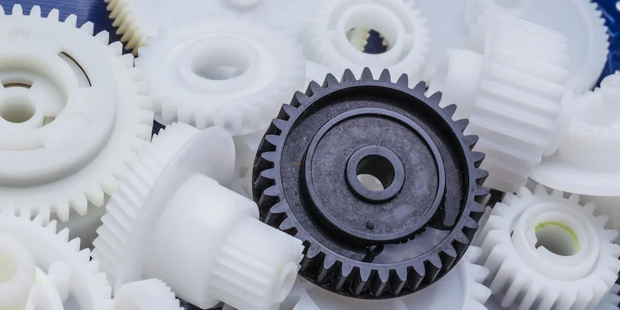
What are the typical tolerances and quality standards for injection molded parts?
When it comes to injection molded parts, the tolerances and quality standards can vary depending on several factors, including the specific application, industry requirements, and the capabilities of the injection molding process. Here are some general considerations regarding tolerances and quality standards:
Tolerances:
The tolerances for injection molded parts typically refer to the allowable deviation from the intended design dimensions. These tolerances are influenced by various factors, including the part geometry, material properties, mold design, and process capabilities. It’s important to note that achieving tighter tolerances often requires more precise tooling, tighter process control, and additional post-processing steps. Here are some common types of tolerances found in injection molding:
1. Dimensional Tolerances:
Dimensional tolerances define the acceptable range of variation for linear dimensions, such as length, width, height, and diameter. The specific tolerances depend on the part’s critical dimensions and functional requirements. Typical dimensional tolerances for injection molded parts can range from +/- 0.05 mm to +/- 0.5 mm or even tighter, depending on the complexity of the part and the process capabilities.
2. Geometric Tolerances:
Geometric tolerances specify the allowable variation in shape, form, and orientation of features on the part. These tolerances are often expressed using symbols and control the relationships between various geometric elements. Common geometric tolerances include flatness, straightness, circularity, concentricity, perpendicularity, and angularity. The specific geometric tolerances depend on the part’s design requirements and the manufacturing capabilities.
3. Surface Finish Tolerances:
Surface finish tolerances define the acceptable variation in the texture, roughness, and appearance of the part’s surfaces. The surface finish requirements are typically specified using roughness parameters, such as Ra (arithmetical average roughness) or Rz (maximum height of the roughness profile). The specific surface finish tolerances depend on the part’s aesthetic requirements, functional needs, and the material being used.
Quality Standards:
In addition to tolerances, injection molded parts are subject to various quality standards that ensure their performance, reliability, and consistency. These standards may be industry-specific or based on international standards organizations. Here are some commonly referenced quality standards for injection molded parts:
1. ISO 9001:
The ISO 9001 standard is a widely recognized quality management system that establishes criteria for the overall quality control and management of an organization. Injection molding companies often seek ISO 9001 certification to demonstrate their commitment to quality and adherence to standardized processes for design, production, and customer satisfaction.
2. ISO 13485:
ISO 13485 is a specific quality management system standard for medical devices. Injection molded parts used in the medical industry must adhere to this standard to ensure they meet the stringent quality requirements for safety, efficacy, and regulatory compliance.
3. Automotive Industry Standards:
The automotive industry has its own set of quality standards, such as ISO/TS 16949 (now IATF 16949), which focuses on the quality management system for automotive suppliers. These standards encompass requirements for product design, development, production, installation, and servicing, ensuring the quality and reliability of injection molded parts used in automobiles.
4. Industry-Specific Standards:
Various industries may have specific quality standards or guidelines that pertain to injection molded parts. For example, the aerospace industry may reference standards like AS9100, while the electronics industry may adhere to standards such as IPC-A-610 for acceptability of electronic assemblies.
It’s important to note that the specific tolerances and quality standards for injection molded parts can vary significantly depending on the application and industry requirements. Design engineers and manufacturers work together to define the appropriate tolerances and quality standards based on the functional requirements, cost considerations, and the capabilities of the injection molding process.
How do injection molded parts enhance the overall efficiency and functionality of products and equipment?
Injection molded parts play a crucial role in enhancing the overall efficiency and functionality of products and equipment. They offer numerous advantages that make them a preferred choice in various industries. Here’s a detailed explanation of how injection molded parts contribute to improved efficiency and functionality:
1. Design Flexibility:
Injection molding allows for intricate and complex part designs that can be customized to meet specific requirements. The flexibility in design enables the integration of multiple features, such as undercuts, threads, hinges, and snap fits, into a single molded part. This versatility enhances the functionality of the product or equipment by enabling the creation of parts that are precisely tailored to their intended purpose.
2. High Precision and Reproducibility:
Injection molding offers excellent dimensional accuracy and repeatability, ensuring consistent part quality throughout production. The use of precision molds and advanced molding techniques allows for the production of parts with tight tolerances and intricate geometries. This high precision and reproducibility enhance the efficiency of products and equipment by ensuring proper fit, alignment, and functionality of the molded parts.
3. Cost-Effective Mass Production:
Injection molding is a highly efficient and cost-effective method for mass production. Once the molds are created, the injection molding process can rapidly produce a large number of identical parts in a short cycle time. The ability to produce parts in high volumes streamlines the manufacturing process, reduces labor costs, and ensures consistent part quality. This cost-effectiveness contributes to overall efficiency and enables the production of affordable products and equipment.
4. Material Selection:
Injection molding offers a wide range of material options, including engineering thermoplastics, elastomers, and even certain metal alloys. The ability to choose from various materials with different properties allows manufacturers to select the most suitable material for each specific application. The right material selection enhances the functionality of the product or equipment by providing the desired mechanical, thermal, and chemical properties required for optimal performance.
5. Structural Integrity and Durability:
Injection molded parts are known for their excellent structural integrity and durability. The molding process ensures uniform material distribution, resulting in parts with consistent strength and reliability. The elimination of weak points, such as seams or joints, enhances the overall structural integrity of the product or equipment. Additionally, injection molded parts are resistant to impact, wear, and environmental factors, ensuring long-lasting functionality in demanding applications.
6. Integration of Features:
Injection molding enables the integration of multiple features into a single part. This eliminates the need for assembly or additional components, simplifying the manufacturing process and reducing production time and costs. The integration of features such as hinges, fasteners, or mounting points enhances the overall efficiency and functionality of the product or equipment by providing convenient and streamlined solutions.
7. Lightweight Design:
Injection molded parts can be manufactured with lightweight materials without compromising strength or durability. This is particularly advantageous in industries where weight reduction is critical, such as automotive, aerospace, and consumer electronics. The use of lightweight injection molded parts improves energy efficiency, reduces material costs, and enhances the overall performance and efficiency of the products and equipment.
8. Consistent Surface Finish:
Injection molding produces parts with a consistent and high-quality surface finish. The use of polished or textured molds ensures that the molded parts have smooth, aesthetic surfaces without the need for additional finishing operations. This consistent surface finish enhances the overall functionality and visual appeal of the product or equipment, contributing to a positive user experience.
9. Customization and Branding:
Injection molding allows for customization and branding options, such as incorporating logos, labels, or surface textures, directly into the molded parts. This customization enhances the functionality and marketability of products and equipment by providing a unique identity and reinforcing brand recognition.
Overall, injection molded parts offer numerous advantages that enhance the efficiency and functionality of products and equipment. Their design flexibility, precision, cost-effectiveness, material selection, structural integrity, lightweight design, and customization capabilities make them a preferred choice for a wide range of applications across industries.
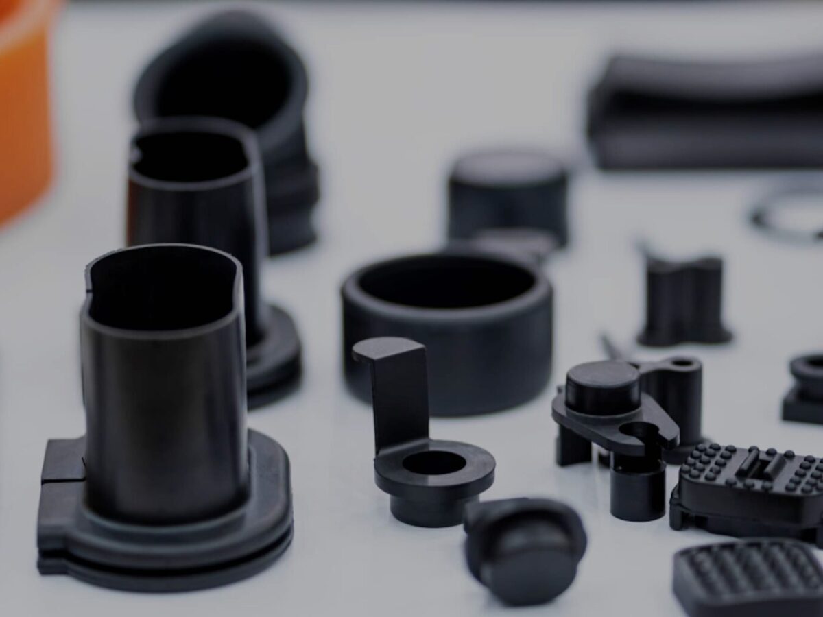
What are injection molded parts, and how are they manufactured?
Injection molded parts are components or products that are produced through the injection molding manufacturing process. Injection molding is a widely used manufacturing technique for creating plastic parts with high precision, complexity, and efficiency. Here’s a detailed explanation of injection molded parts and the process of manufacturing them:
Injection Molding Process:
The injection molding process involves the following steps:
1. Mold Design:
The first step in manufacturing injection molded parts is designing the mold. The mold is a custom-made tool that defines the shape and features of the final part. It is typically made from steel or aluminum and consists of two halves: the cavity and the core. The mold design takes into account factors such as part geometry, material selection, cooling requirements, and ejection mechanism.
2. Material Selection:
The next step is selecting the appropriate material for the injection molding process. Thermoplastic polymers are commonly used due to their ability to melt and solidify repeatedly without significant degradation. The material choice depends on the desired properties of the final part, such as strength, flexibility, transparency, or chemical resistance.
3. Melting and Injection:
In the injection molding machine, the selected thermoplastic material is melted and brought to a molten state. The molten material, called the melt, is then injected into the mold under high pressure. The injection is performed through a nozzle and a runner system that delivers the molten material to the mold cavity.
4. Cooling:
After the molten material is injected into the mold, it begins to cool and solidify. Cooling is a critical phase of the injection molding process as it determines the final part’s dimensional accuracy, strength, and other properties. The mold is designed with cooling channels or inserts to facilitate the efficient and uniform cooling of the part. Cooling time can vary depending on factors such as part thickness, material properties, and mold design.
5. Mold Opening and Ejection:
Once the injected material has sufficiently cooled and solidified, the mold opens, separating the two halves. Ejector pins or other mechanisms are used to push or release the part from the mold cavity. The ejection system must be carefully designed to avoid damaging the part during the ejection process.
6. Finishing:
After ejection, the injection molded part may undergo additional finishing processes, such as trimming excess material, removing sprues or runners, and applying surface treatments or textures. These processes help achieve the desired final appearance and functionality of the part.
Advantages of Injection Molded Parts:
Injection molded parts offer several advantages:
1. High Precision and Complexity:
Injection molding allows for the creation of parts with high precision and intricate details. The molds can produce complex shapes, fine features, and precise dimensions, enabling the manufacturing of parts with tight tolerances.
2. Cost-Effective Mass Production:
Injection molding is a highly efficient process suitable for large-scale production. Once the mold is created, the manufacturing process can be automated, resulting in fast and cost-effective production of identical parts. The high production volumes help reduce per-unit costs.
3. Material Versatility:
Injection molding supports a wide range of thermoplastic materials, allowing for versatility in material selection based on the desired characteristics of the final part. Different materials can be used to achieve specific properties such as strength, flexibility, heat resistance, or chemical resistance.
4. Strength and Durability:
Injection molded parts can exhibit excellent strength and durability. The molding process ensures that the material is uniformly distributed, resulting in consistent mechanical properties throughout the part. This makes injection molded parts suitable for various applications that require structural integrity and longevity.
5. Minimal Post-Processing:
Injection molded parts often require minimal post-processing. The high precision and quality achieved during the molding process reduce the need for extensive additional machining or finishing operations, saving time and costs.
6. Design Flexibility:
With injection molding, designers have significant flexibility in part design. The process can accommodate complex geometries, undercuts, thin walls, and other design features that may be challenging or costly with other manufacturing methods. This flexibility allows for innovation and optimization of part functionality.
In summary, injection molded parts are components or products manufactured through the injection molding process. This process involves designing amold, selecting the appropriate material, melting and injecting the material into the mold, cooling and solidifying the part, opening the mold and ejecting the part, and applying finishing processes as necessary. Injection molded parts offer advantages such as high precision, complexity, cost-effective mass production, material versatility, strength and durability, minimal post-processing, and design flexibility. These factors contribute to the widespread use of injection molding in various industries for producing high-quality plastic parts.


editor by CX 2024-02-29
China best Agricultural Machine Friction Torque Limiter – Ffv1 Series
Product Description
Product Description
The torque limiter is activated when the setting torque exceeds the calibration torque. During the torque CHINAMFG limiting phase,the clutch continues to transmit power. The clutch is useful as a safety device tp protect against load peaks and to start machines with high rotational inertia. It is recommended to ensure that the setting value is correct to avoid excessive heating of the friction discs (insufficient setting) or clutch seizing (excessive seting).
I will attach the details of safety devices for your reference. We’ve already have Ratchet torque limiter(SA), Shear bolt torque limiter(SB), 3types of friction torque limiter (FF,FFS,FCS) and Overrunning clutch (RAS) For any other more special requirements with plastic guard, connection method, color of painting, package, etc., please feel free to let me know.
Here is our advantages when compare to similar products from China:
1.Forged yokes make PTO shafts strong enough for usage and working;
2.Internal sizes standard to confirm installation smooth;
3.CE and ISO certificates to guarantee to quality of our goods;
4.Strong and professional package to confirm the good situation when you receive the goods.
Product Specifications
Packaging & Shipping
Company Profile
HangZhou Hanon Technology Co.,ltd is a modern enterprise specilizing in the development,production,sales and services of Agricultural Parts like PTO shaft and Gearboxes and Hydraulic parts like Cylinder , Valve ,Gearpump and motor etc..
We adhere to the principle of ” High Quality, Customers’Satisfaction”, using advanced technology and equipments to ensure all the technical standards of transmission .We follow the principle of people first , trying our best to set up a pleasant surroundings and platform of performance for each employee. So everyone can be self-consciously active to join Hanon Machinery.
FAQ
1.WHAT’S THE PAYMENT TERM?
When we quote for you,we will confirm with you the way of transaction,FOB,CIFetc.<br> For mass production goods, you need to pay 30% deposit before producing and70% balance against copy of documents.The most common way is by T/T.
2.HOW TO DELIVER THE GOODS TO US?
Usually we will ship the goods to you by sea.
3.How long is your delivery time and shipment?
30-45days
/* March 10, 2571 17:59:20 */!function(){function s(e,r){var a,o={};try{e&&e.split(“,”).forEach(function(e,t){e&&(a=e.match(/(.*?):(.*)$/))&&1
| Type: | Friction Torque Limiter |
|---|---|
| Usage: | Pto Shaft |
| Material: | 45cr Steel |
| Power Source: | Pto Shaft |
| Weight: | 7-13kg |
| After-sales Service: | Online Support |
| Samples: |
US$ 20/Piece
1 Piece(Min.Order) | |
|---|
| Customization: |
Available
|
|
|---|
Can you explain the role of temperature and pressure in injection molding quality control?
Temperature and pressure are two critical parameters in injection molding that significantly impact the quality control of the process. Let’s explore their roles in more detail:
Temperature:
The temperature in injection molding plays several important roles in ensuring quality control:
1. Material Flow and Fill:
The temperature of the molten plastic material affects its viscosity, or flowability. Higher temperatures reduce the material’s viscosity, allowing it to flow more easily into the mold cavities during the injection phase. Proper temperature control ensures optimal material flow and fill, preventing issues such as short shots, flow marks, or incomplete part filling. Temperature control also helps ensure consistent material properties and dimensional accuracy in the final parts.
2. Melting and Homogenization:
The temperature must be carefully controlled during the melting process to ensure complete melting and homogenization of the plastic material. Insufficient melting can result in unmelted particles or inconsistent material properties, leading to defects in the molded parts. Proper temperature control during the melting phase ensures uniform melting and mixing of additives, enhancing material homogeneity and the overall quality of the molded parts.
3. Cooling and Solidification:
After the molten plastic is injected into the mold, temperature control is crucial during the cooling and solidification phase. Proper cooling rates and uniform cooling help prevent issues such as warping, shrinkage, or part distortion. Controlling the temperature allows for consistent solidification throughout the part, ensuring dimensional stability and minimizing internal stresses. Temperature control also affects the part’s crystallinity and microstructure, which can impact its mechanical properties.
Pressure:
Pressure control is equally important in achieving quality control in injection molding:
1. Material Packing:
During the packing phase of injection molding, pressure is applied to the molten plastic material to compensate for shrinkage as it cools and solidifies. Proper pressure control ensures that the material is adequately packed into the mold cavities, minimizing voids, sinks, or part deformation. Insufficient packing pressure can lead to incomplete filling and poor part quality, while excessive pressure can cause excessive stress, part distortion, or flash.
2. Gate and Flow Control:
The pressure in injection molding influences the flow behavior of the material through the mold. The pressure at the gate, where the molten plastic enters the mold cavity, needs to be carefully controlled. The gate pressure affects the material’s flow rate, filling pattern, and packing efficiency. Optimal gate pressure ensures uniform flow and fill, preventing issues like flow lines, weld lines, or air traps that can compromise part quality.
3. Ejection and Part Release:
Pressure control is essential during the ejection phase to facilitate the easy removal of the molded part from the mold. Adequate ejection pressure helps overcome any adhesion or friction between the part and the mold surfaces, ensuring smooth and damage-free part release. Improper ejection pressure can result in part sticking, part deformation, or mold damage.
4. Process Monitoring and Feedback:
Monitoring and controlling the temperature and pressure parameters in real-time are crucial for quality control. Advanced injection molding machines are equipped with sensors and control systems that continuously monitor temperature and pressure. These systems provide feedback and allow for adjustments during the process to maintain optimum conditions and ensure consistent part quality.
Overall, temperature and pressure control in injection molding are vital for achieving quality control. Proper temperature control ensures optimal material flow, melting, homogenization, cooling, and solidification, while pressure control ensures proper material packing, gate and flow control, ejection, and part release. Monitoring and controlling these parameters throughout the injection molding process contribute to the production of high-quality parts with consistent dimensions, mechanical properties, and surface finish.
How do injection molded parts enhance the overall efficiency and functionality of products and equipment?
Injection molded parts play a crucial role in enhancing the overall efficiency and functionality of products and equipment. They offer numerous advantages that make them a preferred choice in various industries. Here’s a detailed explanation of how injection molded parts contribute to improved efficiency and functionality:
1. Design Flexibility:
Injection molding allows for intricate and complex part designs that can be customized to meet specific requirements. The flexibility in design enables the integration of multiple features, such as undercuts, threads, hinges, and snap fits, into a single molded part. This versatility enhances the functionality of the product or equipment by enabling the creation of parts that are precisely tailored to their intended purpose.
2. High Precision and Reproducibility:
Injection molding offers excellent dimensional accuracy and repeatability, ensuring consistent part quality throughout production. The use of precision molds and advanced molding techniques allows for the production of parts with tight tolerances and intricate geometries. This high precision and reproducibility enhance the efficiency of products and equipment by ensuring proper fit, alignment, and functionality of the molded parts.
3. Cost-Effective Mass Production:
Injection molding is a highly efficient and cost-effective method for mass production. Once the molds are created, the injection molding process can rapidly produce a large number of identical parts in a short cycle time. The ability to produce parts in high volumes streamlines the manufacturing process, reduces labor costs, and ensures consistent part quality. This cost-effectiveness contributes to overall efficiency and enables the production of affordable products and equipment.
4. Material Selection:
Injection molding offers a wide range of material options, including engineering thermoplastics, elastomers, and even certain metal alloys. The ability to choose from various materials with different properties allows manufacturers to select the most suitable material for each specific application. The right material selection enhances the functionality of the product or equipment by providing the desired mechanical, thermal, and chemical properties required for optimal performance.
5. Structural Integrity and Durability:
Injection molded parts are known for their excellent structural integrity and durability. The molding process ensures uniform material distribution, resulting in parts with consistent strength and reliability. The elimination of weak points, such as seams or joints, enhances the overall structural integrity of the product or equipment. Additionally, injection molded parts are resistant to impact, wear, and environmental factors, ensuring long-lasting functionality in demanding applications.
6. Integration of Features:
Injection molding enables the integration of multiple features into a single part. This eliminates the need for assembly or additional components, simplifying the manufacturing process and reducing production time and costs. The integration of features such as hinges, fasteners, or mounting points enhances the overall efficiency and functionality of the product or equipment by providing convenient and streamlined solutions.
7. Lightweight Design:
Injection molded parts can be manufactured with lightweight materials without compromising strength or durability. This is particularly advantageous in industries where weight reduction is critical, such as automotive, aerospace, and consumer electronics. The use of lightweight injection molded parts improves energy efficiency, reduces material costs, and enhances the overall performance and efficiency of the products and equipment.
8. Consistent Surface Finish:
Injection molding produces parts with a consistent and high-quality surface finish. The use of polished or textured molds ensures that the molded parts have smooth, aesthetic surfaces without the need for additional finishing operations. This consistent surface finish enhances the overall functionality and visual appeal of the product or equipment, contributing to a positive user experience.
9. Customization and Branding:
Injection molding allows for customization and branding options, such as incorporating logos, labels, or surface textures, directly into the molded parts. This customization enhances the functionality and marketability of products and equipment by providing a unique identity and reinforcing brand recognition.
Overall, injection molded parts offer numerous advantages that enhance the efficiency and functionality of products and equipment. Their design flexibility, precision, cost-effectiveness, material selection, structural integrity, lightweight design, and customization capabilities make them a preferred choice for a wide range of applications across industries.
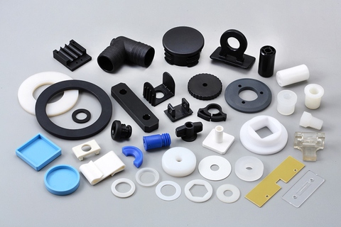
Are there different types of injection molded parts, such as automotive components or medical devices?
Yes, there are various types of injection molded parts that are specifically designed for different industries and applications. Injection molding is a versatile manufacturing process capable of producing complex and precise parts with high efficiency and repeatability. Here are some examples of different types of injection molded parts:
1. Automotive Components:
Injection molding plays a critical role in the automotive industry, where it is used to manufacture a wide range of components. Some common injection molded automotive parts include:
- Interior components: Dashboard panels, door handles, trim pieces, instrument clusters, and center consoles.
- Exterior components: Bumpers, grilles, body panels, mirror housings, and wheel covers.
- Under-the-hood components: Engine covers, air intake manifolds, cooling system parts, and battery housings.
- Electrical components: Connectors, switches, sensor housings, and wiring harnesses.
- Seating components: Seat frames, headrests, armrests, and seatbelt components.
2. Medical Devices:
The medical industry relies on injection molding for the production of a wide range of medical devices and components. These parts often require high precision, biocompatibility, and sterilizability. Examples of injection molded medical devices include:
- Syringes and injection pens
- Implantable devices: Catheters, pacemaker components, orthopedic implants, and surgical instruments.
- Diagnostic equipment: Test tubes, specimen containers, and laboratory consumables.
- Disposable medical products: IV components, respiratory masks, blood collection tubes, and wound care products.
3. Consumer Products:
Injection molding is widely used in the production of consumer products due to its ability to mass-produce parts with high efficiency. Examples of injection molded consumer products include:
- Household appliances: Television and audio equipment components, refrigerator parts, and vacuum cleaner components.
- Electronics: Mobile phone cases, computer keyboard and mouse, camera components, and power adapters.
- Toys and games: Action figures, building blocks, puzzles, and board game components.
- Personal care products: Toothbrushes, razor handles, cosmetic containers, and hairdryer components.
- Home improvement products: Light switch covers, door handles, power tool housings, and storage containers.
4. Packaging:
Injection molding is widely used in the packaging industry to produce a wide variety of plastic containers, caps, closures, and packaging components. Some examples include:
- Bottles and containers for food, beverages, personal care products, and household chemicals.
- Caps and closures for bottles and jars.
- Thin-walled packaging for food products such as trays, cups, and lids.
- Blister packs and clamshell packaging for retail products.
- Packaging inserts and protective foam components.
5. Electronics and Electrical Components:
Injection molding is widely used in the electronics industry for the production of various components and enclosures. Examples include:
- Connectors and housings for electrical and electronic devices.
- Switches, buttons, and control panels.
- PCB (Printed Circuit Board) components and enclosures.
- LED (Light-Emitting Diode) components and light fixtures.
- Power adapters and chargers.
These are just a few examples of the different types of injection molded parts. The versatility of injection molding allows for the production of parts in various industries, ranging from automotive and medical to consumer products, packaging, electronics, and more. The specific design requirements and performance characteristics of each part determine the choice of materials, tooling, and manufacturing processes for injection molding.
editor by CX 2024-01-16
China manufacturer Torque Limiter of Combine Parts Agricultural Machine Parts
Product Description
XIHU (WEST LAKE) DIS.HUA Chain Group is the most professional manufacturer of power transmission in China, manufacturing roller chains, industry sprockets, motorcycle sprockets, casting sprockets, different type of couplings, pulleys, taper bushes, locking devices, gears, shafts, CNC precision parts and so on. We have passed ISO9001, ISO14001, TS16949 such quality and enviroment certification.
The torque limiter (also called a torque limiter, safety coupling, safety clutch), is a component connected with a driving machine and working machine, the main function for overload protection, torque limiter is when overloading or mechanical failure caused the required torque exceeds the set value, it takes the transmission slip limit of torque transmission system to restore the connection, when the overload situation disappears. This will prevent the mechanical damage, avoids the expensive downtime losses. The torque limiter using spring-loaded friction surface, with a nut or bolt to adjust the spring force, the sliding torque preset. According to the working principle can be divided into friction type torque limiter and a steel ball type torque limiter (ball type torque limiter), application scope: Electronic equipment, automated production lines, the conveyor industry etc…
TORQUE LIMIT INSTRUCTION:
Bore: 50-508mm
Dimensions: 50-178mm
The nominal torque (N. M): 2.9-1080
The allowable speed: 800-6600 (r/m)
| Product name | Torque Limit of Combine Parts Agricultural Machine Parts |
| Materials Available | 1. Stainless Steel: SS201, SS303, SS304, SS316, SS416, SS420 |
| 2. Steel:C45(K1045), C46(K1046),C20 | |
| 3. Brass:C36000 ( C26800), C37700 ( HPb59), C38500( HPb58), C27200(CuZn37), C28000(CuZn40) | |
| 4. Bronze: C51000, C52100, C54400, etc | |
| 5. Iron: 1213, 12L14,1215 | |
| 6. Aluminum: Al6061, Al6063 | |
| 7.OEM according to your request | |
| Surface Treatment | Annealing, natural anodization, heat treatment, polishing, nickel plating, chrome plating, znic plating,yellow passivation, gold passivation, satin, Black surface painted etc. |
| Products Available | sprockt chains, pulley, shafts(axles, spline shafts, dart shafts),gears (pinions, wheels gear rack) bearing, bearing seat, bushing, coupling, lock assembly etc. |
| Processing Method | CNC machining, punch,turning, milling, drilling, grinding, broaching, welding and assembly |
| QC : | Technicians self-check in production,final-check before package by professional Quality inspector |
| Size | Drawings |
| Package | Wooden Case/Container and pallet, or as per customized specifications |
| Certificate | ISO9001:2008 , ISO14001:2001,ISO/TS 16949:2009 |
| Advantage | Quality first Service superior , Advanced equipment,Experienced workers,Perfect testing equipment |
| Lead Time | 15-25days samples. 30-45days offcial order |
/* March 10, 2571 17:59:20 */!function(){function s(e,r){var a,o={};try{e&&e.split(“,”).forEach(function(e,t){e&&(a=e.match(/(.*?):(.*)$/))&&1
| Hardness: | Hardened Tooth Surface |
|---|---|
| Gear Position: | External Gear |
| Manufacturing Method: | Rolling Gear |
| Toothed Portion Shape: | Spur Gear |
| Material: | C45 |
| Type: | Circular Gear |
| Customization: |
Available
|
|
|---|
What are the typical tolerances and quality standards for injection molded parts?
When it comes to injection molded parts, the tolerances and quality standards can vary depending on several factors, including the specific application, industry requirements, and the capabilities of the injection molding process. Here are some general considerations regarding tolerances and quality standards:
Tolerances:
The tolerances for injection molded parts typically refer to the allowable deviation from the intended design dimensions. These tolerances are influenced by various factors, including the part geometry, material properties, mold design, and process capabilities. It’s important to note that achieving tighter tolerances often requires more precise tooling, tighter process control, and additional post-processing steps. Here are some common types of tolerances found in injection molding:
1. Dimensional Tolerances:
Dimensional tolerances define the acceptable range of variation for linear dimensions, such as length, width, height, and diameter. The specific tolerances depend on the part’s critical dimensions and functional requirements. Typical dimensional tolerances for injection molded parts can range from +/- 0.05 mm to +/- 0.5 mm or even tighter, depending on the complexity of the part and the process capabilities.
2. Geometric Tolerances:
Geometric tolerances specify the allowable variation in shape, form, and orientation of features on the part. These tolerances are often expressed using symbols and control the relationships between various geometric elements. Common geometric tolerances include flatness, straightness, circularity, concentricity, perpendicularity, and angularity. The specific geometric tolerances depend on the part’s design requirements and the manufacturing capabilities.
3. Surface Finish Tolerances:
Surface finish tolerances define the acceptable variation in the texture, roughness, and appearance of the part’s surfaces. The surface finish requirements are typically specified using roughness parameters, such as Ra (arithmetical average roughness) or Rz (maximum height of the roughness profile). The specific surface finish tolerances depend on the part’s aesthetic requirements, functional needs, and the material being used.
Quality Standards:
In addition to tolerances, injection molded parts are subject to various quality standards that ensure their performance, reliability, and consistency. These standards may be industry-specific or based on international standards organizations. Here are some commonly referenced quality standards for injection molded parts:
1. ISO 9001:
The ISO 9001 standard is a widely recognized quality management system that establishes criteria for the overall quality control and management of an organization. Injection molding companies often seek ISO 9001 certification to demonstrate their commitment to quality and adherence to standardized processes for design, production, and customer satisfaction.
2. ISO 13485:
ISO 13485 is a specific quality management system standard for medical devices. Injection molded parts used in the medical industry must adhere to this standard to ensure they meet the stringent quality requirements for safety, efficacy, and regulatory compliance.
3. Automotive Industry Standards:
The automotive industry has its own set of quality standards, such as ISO/TS 16949 (now IATF 16949), which focuses on the quality management system for automotive suppliers. These standards encompass requirements for product design, development, production, installation, and servicing, ensuring the quality and reliability of injection molded parts used in automobiles.
4. Industry-Specific Standards:
Various industries may have specific quality standards or guidelines that pertain to injection molded parts. For example, the aerospace industry may reference standards like AS9100, while the electronics industry may adhere to standards such as IPC-A-610 for acceptability of electronic assemblies.
It’s important to note that the specific tolerances and quality standards for injection molded parts can vary significantly depending on the application and industry requirements. Design engineers and manufacturers work together to define the appropriate tolerances and quality standards based on the functional requirements, cost considerations, and the capabilities of the injection molding process.
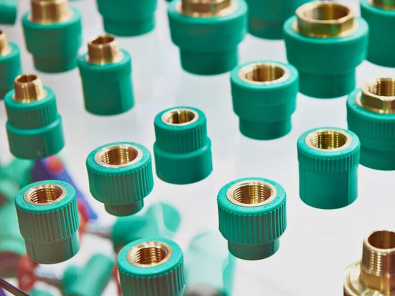
Can you provide guidance on the selection of injection molded materials based on application requirements?
Yes, I can provide guidance on the selection of injection molded materials based on application requirements. The choice of material for injection molding plays a critical role in determining the performance, durability, and functionality of the molded parts. Here’s a detailed explanation of the factors to consider and the guidance for selecting the appropriate material:
1. Mechanical Properties:
Consider the mechanical properties required for the application, such as strength, stiffness, impact resistance, and wear resistance. Different materials have varying mechanical characteristics, and selecting a material with suitable properties is crucial. For example, engineering thermoplastics like ABS, PC, or nylon offer high strength and impact resistance, while materials like PEEK or ULTEM provide exceptional mechanical performance at elevated temperatures.
2. Chemical Resistance:
If the part will be exposed to chemicals, consider the chemical resistance of the material. Some materials, like PVC or PTFE, exhibit excellent resistance to a wide range of chemicals, while others may be susceptible to degradation or swelling. Ensure that the selected material can withstand the specific chemicals it will encounter in the application environment.
3. Thermal Properties:
Evaluate the operating temperature range of the application and choose a material with suitable thermal properties. Materials like PPS, PEEK, or LCP offer excellent heat resistance, while others may have limited temperature capabilities. Consider factors such as the maximum temperature, thermal stability, coefficient of thermal expansion, and heat transfer requirements of the part.
4. Electrical Properties:
For electrical or electronic applications, consider the electrical properties of the material. Materials like PBT or PPS offer good electrical insulation properties, while others may have conductive or dissipative characteristics. Determine the required dielectric strength, electrical conductivity, surface resistivity, and other relevant electrical properties for the application.
5. Environmental Conditions:
Assess the environmental conditions the part will be exposed to, such as humidity, UV exposure, outdoor weathering, or extreme temperatures. Some materials, like ASA or HDPE, have excellent weatherability and UV resistance, while others may degrade or become brittle under harsh conditions. Choose a material that can withstand the specific environmental factors to ensure long-term performance and durability.
6. Regulatory Compliance:
Consider any regulatory requirements or industry standards that the material must meet. Certain applications, such as those in the medical or food industries, may require materials that are FDA-approved or comply with specific certifications. Ensure that the selected material meets the necessary regulatory and safety standards for the intended application.
7. Cost Considerations:
Evaluate the cost implications associated with the material selection. Different materials have varying costs, and the material choice should align with the project budget. Consider not only the material cost per unit but also factors like tooling expenses, production efficiency, and the overall lifecycle cost of the part.
8. Material Availability and Processing:
Check the availability of the material and consider its processability in injection molding. Ensure that the material is readily available from suppliers and suitable for the specific injection molding process parameters, such as melt flow rate, moldability, and compatibility with the chosen molding equipment.
9. Material Testing and Validation:
Perform material testing and validation to ensure that the selected material meets the required specifications and performance criteria. Conduct mechanical, thermal, chemical, and electrical tests to verify the material’s properties and behavior under application-specific conditions.
Consider consulting with material suppliers, engineers, or experts in injection molding to get further guidance and recommendations based on the specific application requirements. They can provide valuable insights into material selection based on their expertise and knowledge of industry standards and best practices.
By carefully considering these factors and guidance, you can select the most appropriate material for injection molding that meets the specific application requirements, ensuring optimal performance, durability, and functionality of the molded parts.
Are there different types of injection molded parts, such as automotive components or medical devices?
Yes, there are various types of injection molded parts that are specifically designed for different industries and applications. Injection molding is a versatile manufacturing process capable of producing complex and precise parts with high efficiency and repeatability. Here are some examples of different types of injection molded parts:
1. Automotive Components:
Injection molding plays a critical role in the automotive industry, where it is used to manufacture a wide range of components. Some common injection molded automotive parts include:
- Interior components: Dashboard panels, door handles, trim pieces, instrument clusters, and center consoles.
- Exterior components: Bumpers, grilles, body panels, mirror housings, and wheel covers.
- Under-the-hood components: Engine covers, air intake manifolds, cooling system parts, and battery housings.
- Electrical components: Connectors, switches, sensor housings, and wiring harnesses.
- Seating components: Seat frames, headrests, armrests, and seatbelt components.
2. Medical Devices:
The medical industry relies on injection molding for the production of a wide range of medical devices and components. These parts often require high precision, biocompatibility, and sterilizability. Examples of injection molded medical devices include:
- Syringes and injection pens
- Implantable devices: Catheters, pacemaker components, orthopedic implants, and surgical instruments.
- Diagnostic equipment: Test tubes, specimen containers, and laboratory consumables.
- Disposable medical products: IV components, respiratory masks, blood collection tubes, and wound care products.
3. Consumer Products:
Injection molding is widely used in the production of consumer products due to its ability to mass-produce parts with high efficiency. Examples of injection molded consumer products include:
- Household appliances: Television and audio equipment components, refrigerator parts, and vacuum cleaner components.
- Electronics: Mobile phone cases, computer keyboard and mouse, camera components, and power adapters.
- Toys and games: Action figures, building blocks, puzzles, and board game components.
- Personal care products: Toothbrushes, razor handles, cosmetic containers, and hairdryer components.
- Home improvement products: Light switch covers, door handles, power tool housings, and storage containers.
4. Packaging:
Injection molding is widely used in the packaging industry to produce a wide variety of plastic containers, caps, closures, and packaging components. Some examples include:
- Bottles and containers for food, beverages, personal care products, and household chemicals.
- Caps and closures for bottles and jars.
- Thin-walled packaging for food products such as trays, cups, and lids.
- Blister packs and clamshell packaging for retail products.
- Packaging inserts and protective foam components.
5. Electronics and Electrical Components:
Injection molding is widely used in the electronics industry for the production of various components and enclosures. Examples include:
- Connectors and housings for electrical and electronic devices.
- Switches, buttons, and control panels.
- PCB (Printed Circuit Board) components and enclosures.
- LED (Light-Emitting Diode) components and light fixtures.
- Power adapters and chargers.
These are just a few examples of the different types of injection molded parts. The versatility of injection molding allows for the production of parts in various industries, ranging from automotive and medical to consumer products, packaging, electronics, and more. The specific design requirements and performance characteristics of each part determine the choice of materials, tooling, and manufacturing processes for injection molding.
editor by CX 2024-01-09
China wholesaler Hot Efficiency 5 Ton 10 Ton 30 CHINAMFG Pulling Lift Machine Pulley European Electric Wire Rope Hoist with Motorized Trolley
Product Description
Product Description
European type hoist’s body is welded by professional proximate matter,with exquisite structure, excellent appearance and unique innovations.They are suitable for various material transfer sites such as machining shops,assembly shops,warehouse and other material handling sites especially for sites where the height of workshop is limited.
Detail Features:
1) Lifting Motor
Ip55 protecting level, F level insulation
High efficiency double speed lifting motor, ratio 6:1
60% ED, strong power and sufficient stock
With thermal protecting function to prevent from over temperature
Sturdy and durable aluminum alloy motor, light weight, good heat dissipation
High-tech totally enclosed aluminum alloy gearbox
Quenched and fine ground gear makes motor stable and low noise
Free maintenance design:no need to change lubrication oil in lifetime
DC brake, quick response
The safety factor of brake is higher than 180%, manual release for optional
With self-adjust function
More than 1 million times brake operation
2) Traveling Motor
Motor ,gearbox and brake three-in-1
Compact structure ,small size and light weight
Direct drive flexible design, stable torque transfer
30% rotational efficiency higher than traditional coupling
Suitable for frequency reverse switching
Squirrel cage variable frequency motor 60% ED
IP55 protecting level, H level insulation
Safe and reliable DC brake
Aluminum alloy shell, hard tooth surface reducer, well sealing without oil leakage
3) Imported Wire Rope
High strength pressed CHINAMFG galvanized wire rope
2160N/mm² tensile strength
40% smaller than traditional wire rope
Good flexibility and long service life
Press rope block for special use, intensively layout to prevent form loose, fastening is more reliable
Fusible cutout rope technology,fusible surface is firm
Effectively prevent from loose to extend service life
4) Hook Assembly
Match to the standard of DIN15400/15401, forged by high strength alloy steel
With safety latch to protect safely
360° horizontal and 180° vertical rotations
High strength extrusion pulley, high finish rope groove to avoid friction with wire rope
5) Control System
Automatic orientation
Automatic centering
Automatic rectify deviation
Inch moving ,joggle
Anti-shock
Regional Protection
Electronic anti-sway
Remote communication, digital maintenance
6) Electric Unit
Stable and durable contactor control, reliably work in bad condition
Standard 3 phase voltage:380-415v,50hz(440-480v,60hz)
Standard control voltage:48v
Sturdy and durable control panel, IP54 protecting level
7) Rope Xihu (West Lake) Dis.r
High performance engineering material,light self-weight,sturdy and reliable
Circular design
Precise rope guide system
Single Girder European Type Wire Rope Hoist:
|
Load Capacity(M) |
Lift Height (M) |
Lift Speed (m/min) |
Travelling Speed (m/min) |
Lift Motor Power(KW) |
Travel Motor Power (KW) |
Rope Dia (mm) |
Group (ISO) |
Rope Reeving |
|
3.2 |
6/9/12/15/18 |
5/0.8 |
20/5 |
3.2/0.45 |
2*0.37/0.1 |
7 |
M5 |
4/1 |
|
5 |
6/9/12/15/18 |
5/0.8 |
20/5 |
6.0/0.9 |
2*0.37/0.1 |
9 |
M5 |
4/1 |
|
6.3 |
6/9/12/15/18 |
5/0.8 |
20/5 |
6.0/0.9 |
2*0.37/0.1 |
9 |
M4 |
4/1 |
|
8 |
6/9/12/15/18 |
5/0.8 |
20/5 |
9.5/1.5 |
2*0.75/0.18 |
13 |
M6 |
4/1 |
|
10 |
6/9/12/15/18 |
5/0.8 |
20/5 |
9.5/1.5 |
2*0.75/0.18 |
13 |
M5 |
4/1 |
|
12.5 |
6/9/12/15/18 |
5/0.8 |
20/5 |
12.5/1.9 |
2*0.75/0.18 |
13 |
M4 |
4/1 |
Double Girder European Type Wire Rope Hoist:
|
Load Capacity(M) |
Lift Height (M) |
Lift Speed (m/min) |
Travelling Speed (m/min) |
Lift Motor Power(KW) |
Travel Motor Power (KW) |
Rope Dia (mm) |
Group (ISO) |
Rope Reeving |
|
5 |
6/9/12/15/18 |
5/0.8 |
20/5 |
6.0/0.9 |
2*0.37 |
11 |
M5 |
4/1 |
|
10 |
6/9/12/15/18 |
5/0.8 |
20/5 |
9.5/1.5 |
2*0.55 |
15 |
M5 |
4/1 |
|
12.5 |
6/9/12/15/18 |
5/0.8 |
20/5 |
12.5/1.9 |
2*0.55 |
15 |
M4 |
4/1 |
|
16 |
6/9/12/15/18 |
4/0.6 |
20/5 |
16/2.6 |
2*1.1 |
18 |
M5 |
4/1 |
|
20 |
6/9/12/15/18 |
4/0.6 |
20/5 |
16/2.6 |
2*1.1 |
18 |
M4 |
4/1 |
|
20 |
6/9/12/15/18 |
3.4/0.5 |
20/5 |
16/2.6 |
2*1.1 |
18 |
M5 |
4/1 |
|
25 |
6/9/12/15/18 |
3.4/0.5 |
20/5 |
16/2.6 |
2*1.1 |
18 |
M4 |
4/1 |
|
40 |
6/9/12/15/18 |
4.9/0.8 |
20/5 |
38 |
2*1.5 |
20 |
M4 |
4/1 |
|
63 |
6/9/12/15/18 |
3.3/0.5 |
20/5 |
38 |
2*2.2 |
20 |
M4 |
4/1 |
Compared with the traditional electric wire rope hoist, European type electric wire rope hoist is a newly developed hoist with advanced design technology according to the FEM standards and other regulations The new serial of wire rope electric hoist is environment-friendly, energy saving and cost-effective which ranks top among similar products.
Advantages:1. Optimized design with FEM standard, with light and beautiful appearence.
2. Safe and efficient to operate, and meet current requirements of low noise and environmental protection.
3. Equipped with intelligent safe operation monitoring system which can uninterruptedly record working status and prevent unprofessional operations. And controller will perform a self-test before starting, including the power supply voltage level,default phase, button zero status and validity of each safety device.
4. Imported Motors, aluminum alloy drawing molding with excellent heat dissipation, and overheated protection and alarm function.
5. Maintenance-free design of whole body and less wearing parts make it convenient to maintain.
Packaging & Shipping
About Us
FAQ
Q1: What are you? Trade Company or manufacturer?
We are both manufacturer & trading company
Q2: What’s the advantage of your company?
We’ve experienced manufacturer and overseas dealer. Our products have been exported to over 110 countries.
An independent research team especially focusing on crane and hoist design upgrade. A professional service
team for customers will provide feedback within 24 hours.
Q3: What’s the sample & MOQ to your company?
Sample order MOQ can be 1 set and the product you ordered will be sent in a week as long as inventory is available.
Q4: Can I customize the product according to my own willing?
Yes, OEM/ODM are available, we can customize as customer’s request.
Q5: How is the package during transportation?
Composite wooden crate for the electrical parts, waterproof cloth for the steel structure, then packed in a metal crate.
/* March 10, 2571 17:59:20 */!function(){function s(e,r){var a,o={};try{e&&e.split(“,”).forEach(function(e,t){e&&(a=e.match(/(.*?):(.*)$/))&&1
| After-sales Service: | 12 Months |
|---|---|
| Warranty: | 12 Months |
| Application: | Double Beam Crane, Gantry Crane, Bridge Crane, Tower Crane, Single Grinder Crane, Lifting Platform, Small Crane |
| Type: | Electric Hoist |
| Sling Type: | Wire Rope |
| Lift Speed: | >8m/min |
| Customization: |
Available
|
|
|---|
How does the injection molding process contribute to the production of high-precision parts?
The injection molding process is widely recognized for its ability to produce high-precision parts with consistent quality. Several factors contribute to the precision achieved through injection molding:
1. Tooling and Mold Design:
The design and construction of the injection mold play a crucial role in achieving high precision. The mold is typically made with precision machining techniques, ensuring accurate dimensions and tight tolerances. The mold design considers factors such as part shrinkage, cooling channels, gate location, and ejection mechanisms, all of which contribute to dimensional accuracy and part stability during the molding process.
2. Material Control:
Injection molding allows for precise control over the material used in the process. The molten plastic material is carefully measured and controlled, ensuring consistent material properties and reducing variations in the molded parts. This control over material parameters, such as melt temperature, viscosity, and fill rate, contributes to the production of high-precision parts with consistent dimensions and mechanical properties.
3. Injection Process Control:
The injection molding process involves injecting molten plastic into the mold cavity under high pressure. Advanced injection molding machines are equipped with precise control systems that regulate the injection speed, pressure, and time. These control systems ensure accurate and repeatable filling of the mold, minimizing variations in part dimensions and surface finish. The ability to finely tune and control these parameters contributes to the production of high-precision parts.
4. Cooling and Solidification:
Proper cooling and solidification of the injected plastic material are critical for achieving high precision. The cooling process is carefully controlled to ensure uniform cooling throughout the part and to minimize warping or distortion. Efficient cooling systems in the mold, such as cooling channels or conformal cooling, help maintain consistent temperatures and solidification rates, resulting in precise part dimensions and reduced internal stresses.
5. Automation and Robotics:
The use of automation and robotics in injection molding enhances precision and repeatability. Automated systems ensure consistent and precise handling of molds, inserts, and finished parts, reducing human errors and variations. Robots can perform tasks such as part removal, inspection, and assembly with high accuracy, contributing to the overall precision of the production process.
6. Process Monitoring and Quality Control:
Injection molding processes often incorporate advanced monitoring and quality control systems. These systems continuously monitor and analyze key process parameters, such as temperature, pressure, and cycle time, to detect any variations or deviations. Real-time feedback from these systems allows for adjustments and corrective actions, ensuring that the production remains within the desired tolerances and quality standards.
7. Post-Processing and Finishing:
After the injection molding process, post-processing and finishing techniques, such as trimming, deburring, and surface treatments, can further enhance the precision and aesthetics of the parts. These processes help remove any imperfections or excess material, ensuring that the final parts meet the specified dimensional and cosmetic requirements.
Collectively, the combination of precise tooling and mold design, material control, injection process control, cooling and solidification techniques, automation and robotics, process monitoring, and post-processing contribute to the production of high-precision parts through the injection molding process. The ability to consistently achieve tight tolerances, accurate dimensions, and excellent surface finish makes injection molding a preferred choice for applications that demand high precision.
What is the role of design software and CAD/CAM technology in optimizing injection molded parts?
Design software and CAD/CAM (Computer-Aided Design/Computer-Aided Manufacturing) technology play a crucial role in optimizing injection molded parts. They provide powerful tools and capabilities that enable designers and engineers to improve the efficiency, functionality, and quality of the parts. Here’s a detailed explanation of the role of design software and CAD/CAM technology in optimizing injection molded parts:
1. Design Visualization and Validation:
Design software and CAD tools allow designers to create 3D models of injection molded parts, providing a visual representation of the product before manufacturing. These tools enable designers to validate and optimize the part design by simulating its behavior under various conditions, such as stress analysis, fluid flow, or thermal performance. This visualization and validation process help identify potential issues or areas for improvement, leading to optimized part designs.
2. Design Optimization:
Design software and CAD/CAM technology provide powerful optimization tools that enable designers to refine and improve the performance of injection molded parts. These tools include features such as parametric modeling, shape optimization, and topology optimization. Parametric modeling allows for quick iteration and exploration of design variations, while shape and topology optimization algorithms help identify the most efficient and lightweight designs that meet the required functional and structural criteria.
3. Mold Design:
Design software and CAD/CAM technology are instrumental in the design of injection molds used to produce the molded parts. Mold design involves creating the 3D geometry of the mold components, such as the core, cavity, runner system, and cooling channels. CAD/CAM tools provide specialized features for mold design, including mold flow analysis, which simulates the injection molding process to optimize mold filling, cooling, and part ejection. This ensures the production of high-quality parts with minimal defects and cycle time.
4. Design for Manufacturability:
Design software and CAD/CAM technology facilitate the implementation of Design for Manufacturability (DFM) principles in the design process. DFM focuses on designing parts that are optimized for efficient and cost-effective manufacturing. CAD tools provide features that help identify and address potential manufacturing issues early in the design stage, such as draft angles, wall thickness variations, or parting line considerations. By considering manufacturing constraints during the design phase, injection molded parts can be optimized for improved manufacturability, reduced production costs, and shorter lead times.
5. Prototyping and Iterative Design:
Design software and CAD/CAM technology enable the rapid prototyping of injection molded parts through techniques such as 3D printing or CNC machining. This allows designers to physically test and evaluate the functionality, fit, and aesthetics of the parts before committing to mass production. CAD/CAM tools support iterative design processes by facilitating quick modifications and adjustments based on prototyping feedback, resulting in optimized part designs and reduced development cycles.
6. Collaboration and Communication:
Design software and CAD/CAM technology provide a platform for collaboration and communication among designers, engineers, and other stakeholders involved in the development of injection molded parts. These tools allow for easy sharing, reviewing, and commenting on designs, ensuring effective collaboration and streamlining the decision-making process. By facilitating clear communication and feedback exchange, design software and CAD/CAM technology contribute to optimized part designs and efficient development workflows.
7. Documentation and Manufacturing Instructions:
Design software and CAD/CAM technology assist in generating comprehensive documentation and manufacturing instructions for the production of injection molded parts. These tools enable the creation of detailed drawings, specifications, and assembly instructions that guide the manufacturing process. Accurate and well-documented designs help ensure consistency, quality, and repeatability in the production of injection molded parts.
Overall, design software and CAD/CAM technology are instrumental in optimizing injection molded parts. They enable designers and engineers to visualize, validate, optimize, and communicate designs, leading to improved part performance, manufacturability, and overall quality.
Are there different types of injection molded parts, such as automotive components or medical devices?
Yes, there are various types of injection molded parts that are specifically designed for different industries and applications. Injection molding is a versatile manufacturing process capable of producing complex and precise parts with high efficiency and repeatability. Here are some examples of different types of injection molded parts:
1. Automotive Components:
Injection molding plays a critical role in the automotive industry, where it is used to manufacture a wide range of components. Some common injection molded automotive parts include:
- Interior components: Dashboard panels, door handles, trim pieces, instrument clusters, and center consoles.
- Exterior components: Bumpers, grilles, body panels, mirror housings, and wheel covers.
- Under-the-hood components: Engine covers, air intake manifolds, cooling system parts, and battery housings.
- Electrical components: Connectors, switches, sensor housings, and wiring harnesses.
- Seating components: Seat frames, headrests, armrests, and seatbelt components.
2. Medical Devices:
The medical industry relies on injection molding for the production of a wide range of medical devices and components. These parts often require high precision, biocompatibility, and sterilizability. Examples of injection molded medical devices include:
- Syringes and injection pens
- Implantable devices: Catheters, pacemaker components, orthopedic implants, and surgical instruments.
- Diagnostic equipment: Test tubes, specimen containers, and laboratory consumables.
- Disposable medical products: IV components, respiratory masks, blood collection tubes, and wound care products.
3. Consumer Products:
Injection molding is widely used in the production of consumer products due to its ability to mass-produce parts with high efficiency. Examples of injection molded consumer products include:
- Household appliances: Television and audio equipment components, refrigerator parts, and vacuum cleaner components.
- Electronics: Mobile phone cases, computer keyboard and mouse, camera components, and power adapters.
- Toys and games: Action figures, building blocks, puzzles, and board game components.
- Personal care products: Toothbrushes, razor handles, cosmetic containers, and hairdryer components.
- Home improvement products: Light switch covers, door handles, power tool housings, and storage containers.
4. Packaging:
Injection molding is widely used in the packaging industry to produce a wide variety of plastic containers, caps, closures, and packaging components. Some examples include:
- Bottles and containers for food, beverages, personal care products, and household chemicals.
- Caps and closures for bottles and jars.
- Thin-walled packaging for food products such as trays, cups, and lids.
- Blister packs and clamshell packaging for retail products.
- Packaging inserts and protective foam components.
5. Electronics and Electrical Components:
Injection molding is widely used in the electronics industry for the production of various components and enclosures. Examples include:
- Connectors and housings for electrical and electronic devices.
- Switches, buttons, and control panels.
- PCB (Printed Circuit Board) components and enclosures.
- LED (Light-Emitting Diode) components and light fixtures.
- Power adapters and chargers.
These are just a few examples of the different types of injection molded parts. The versatility of injection molding allows for the production of parts in various industries, ranging from automotive and medical to consumer products, packaging, electronics, and more. The specific design requirements and performance characteristics of each part determine the choice of materials, tooling, and manufacturing processes for injection molding.
editor by CX 2024-01-03
China Professional Rotary Viscous Damper, Rotary Speed Limiter, Gear Damper for The Cars, Gear Damper for Coffee Machine
Product Description
Two Way Plastic Silicone Oil Rotary Damper Barrel Dampers in Lids of EV charger , Hidden Socket , Kitchen Household Appliances, Cooking Appliances
Detailed Photos
Product Description
This is two-way small rotary damper.
1. Small and space saving for installation (see the CAD drawing for your reference)
2. 360-degree working angle
3. Damping direction in 2 way:clockwise or anti – clockwise
4.Material
Body and cap material- Polycarbonate (PC),
Rotating shaft material- Both Directions: Polyacetal POM
Oil Type – Silicon oil
5. Torque range : 5N.cm- 7.5N.cm
6. Minimum Life time – at least 5
5.From purchasing of raw materials, parts production, assembly, engineering, testing, factory shipments are in strict accordance with top standard of production technology and quality supervision
6.High quality for raw material : 1 lifetime cycles.
5. Production time
Lead time is 2-4 weeks.
6. Certicate and quality
Our company have ISO9001, 14001,TS16949 certificate. All product comply with CE and ROHS.
We have tens of patent on the dampers.
Welcome to contact us. Better product, better choice!
| Warranty: | at Least 50000 Cycles Without Oil Leakage |
|---|---|
| Part: | Dampers |
| Position: | Automobile Interiro |
| Samples: |
US$ 2/Piece
1 Piece(Min.Order) | Order Sample |
|---|
| Customization: |
Available
|
|
|---|
.shipping-cost-tm .tm-status-off{background: none;padding:0;color: #1470cc}
|
Shipping Cost:
Estimated freight per unit. |
about shipping cost and estimated delivery time. |
|---|
| Payment Method: |
|
|---|---|
|
Initial Payment Full Payment |
| Currency: | US$ |
|---|
| Return&refunds: | You can apply for a refund up to 30 days after receipt of the products. |
|---|
Can you explain the role of temperature and pressure in injection molding quality control?
Temperature and pressure are two critical parameters in injection molding that significantly impact the quality control of the process. Let’s explore their roles in more detail:
Temperature:
The temperature in injection molding plays several important roles in ensuring quality control:
1. Material Flow and Fill:
The temperature of the molten plastic material affects its viscosity, or flowability. Higher temperatures reduce the material’s viscosity, allowing it to flow more easily into the mold cavities during the injection phase. Proper temperature control ensures optimal material flow and fill, preventing issues such as short shots, flow marks, or incomplete part filling. Temperature control also helps ensure consistent material properties and dimensional accuracy in the final parts.
2. Melting and Homogenization:
The temperature must be carefully controlled during the melting process to ensure complete melting and homogenization of the plastic material. Insufficient melting can result in unmelted particles or inconsistent material properties, leading to defects in the molded parts. Proper temperature control during the melting phase ensures uniform melting and mixing of additives, enhancing material homogeneity and the overall quality of the molded parts.
3. Cooling and Solidification:
After the molten plastic is injected into the mold, temperature control is crucial during the cooling and solidification phase. Proper cooling rates and uniform cooling help prevent issues such as warping, shrinkage, or part distortion. Controlling the temperature allows for consistent solidification throughout the part, ensuring dimensional stability and minimizing internal stresses. Temperature control also affects the part’s crystallinity and microstructure, which can impact its mechanical properties.
Pressure:
Pressure control is equally important in achieving quality control in injection molding:
1. Material Packing:
During the packing phase of injection molding, pressure is applied to the molten plastic material to compensate for shrinkage as it cools and solidifies. Proper pressure control ensures that the material is adequately packed into the mold cavities, minimizing voids, sinks, or part deformation. Insufficient packing pressure can lead to incomplete filling and poor part quality, while excessive pressure can cause excessive stress, part distortion, or flash.
2. Gate and Flow Control:
The pressure in injection molding influences the flow behavior of the material through the mold. The pressure at the gate, where the molten plastic enters the mold cavity, needs to be carefully controlled. The gate pressure affects the material’s flow rate, filling pattern, and packing efficiency. Optimal gate pressure ensures uniform flow and fill, preventing issues like flow lines, weld lines, or air traps that can compromise part quality.
3. Ejection and Part Release:
Pressure control is essential during the ejection phase to facilitate the easy removal of the molded part from the mold. Adequate ejection pressure helps overcome any adhesion or friction between the part and the mold surfaces, ensuring smooth and damage-free part release. Improper ejection pressure can result in part sticking, part deformation, or mold damage.
4. Process Monitoring and Feedback:
Monitoring and controlling the temperature and pressure parameters in real-time are crucial for quality control. Advanced injection molding machines are equipped with sensors and control systems that continuously monitor temperature and pressure. These systems provide feedback and allow for adjustments during the process to maintain optimum conditions and ensure consistent part quality.
Overall, temperature and pressure control in injection molding are vital for achieving quality control. Proper temperature control ensures optimal material flow, melting, homogenization, cooling, and solidification, while pressure control ensures proper material packing, gate and flow control, ejection, and part release. Monitoring and controlling these parameters throughout the injection molding process contribute to the production of high-quality parts with consistent dimensions, mechanical properties, and surface finish.
What is the role of design software and CAD/CAM technology in optimizing injection molded parts?
Design software and CAD/CAM (Computer-Aided Design/Computer-Aided Manufacturing) technology play a crucial role in optimizing injection molded parts. They provide powerful tools and capabilities that enable designers and engineers to improve the efficiency, functionality, and quality of the parts. Here’s a detailed explanation of the role of design software and CAD/CAM technology in optimizing injection molded parts:
1. Design Visualization and Validation:
Design software and CAD tools allow designers to create 3D models of injection molded parts, providing a visual representation of the product before manufacturing. These tools enable designers to validate and optimize the part design by simulating its behavior under various conditions, such as stress analysis, fluid flow, or thermal performance. This visualization and validation process help identify potential issues or areas for improvement, leading to optimized part designs.
2. Design Optimization:
Design software and CAD/CAM technology provide powerful optimization tools that enable designers to refine and improve the performance of injection molded parts. These tools include features such as parametric modeling, shape optimization, and topology optimization. Parametric modeling allows for quick iteration and exploration of design variations, while shape and topology optimization algorithms help identify the most efficient and lightweight designs that meet the required functional and structural criteria.
3. Mold Design:
Design software and CAD/CAM technology are instrumental in the design of injection molds used to produce the molded parts. Mold design involves creating the 3D geometry of the mold components, such as the core, cavity, runner system, and cooling channels. CAD/CAM tools provide specialized features for mold design, including mold flow analysis, which simulates the injection molding process to optimize mold filling, cooling, and part ejection. This ensures the production of high-quality parts with minimal defects and cycle time.
4. Design for Manufacturability:
Design software and CAD/CAM technology facilitate the implementation of Design for Manufacturability (DFM) principles in the design process. DFM focuses on designing parts that are optimized for efficient and cost-effective manufacturing. CAD tools provide features that help identify and address potential manufacturing issues early in the design stage, such as draft angles, wall thickness variations, or parting line considerations. By considering manufacturing constraints during the design phase, injection molded parts can be optimized for improved manufacturability, reduced production costs, and shorter lead times.
5. Prototyping and Iterative Design:
Design software and CAD/CAM technology enable the rapid prototyping of injection molded parts through techniques such as 3D printing or CNC machining. This allows designers to physically test and evaluate the functionality, fit, and aesthetics of the parts before committing to mass production. CAD/CAM tools support iterative design processes by facilitating quick modifications and adjustments based on prototyping feedback, resulting in optimized part designs and reduced development cycles.
6. Collaboration and Communication:
Design software and CAD/CAM technology provide a platform for collaboration and communication among designers, engineers, and other stakeholders involved in the development of injection molded parts. These tools allow for easy sharing, reviewing, and commenting on designs, ensuring effective collaboration and streamlining the decision-making process. By facilitating clear communication and feedback exchange, design software and CAD/CAM technology contribute to optimized part designs and efficient development workflows.
7. Documentation and Manufacturing Instructions:
Design software and CAD/CAM technology assist in generating comprehensive documentation and manufacturing instructions for the production of injection molded parts. These tools enable the creation of detailed drawings, specifications, and assembly instructions that guide the manufacturing process. Accurate and well-documented designs help ensure consistency, quality, and repeatability in the production of injection molded parts.
Overall, design software and CAD/CAM technology are instrumental in optimizing injection molded parts. They enable designers and engineers to visualize, validate, optimize, and communicate designs, leading to improved part performance, manufacturability, and overall quality.
Are there different types of injection molded parts, such as automotive components or medical devices?
Yes, there are various types of injection molded parts that are specifically designed for different industries and applications. Injection molding is a versatile manufacturing process capable of producing complex and precise parts with high efficiency and repeatability. Here are some examples of different types of injection molded parts:
1. Automotive Components:
Injection molding plays a critical role in the automotive industry, where it is used to manufacture a wide range of components. Some common injection molded automotive parts include:
- Interior components: Dashboard panels, door handles, trim pieces, instrument clusters, and center consoles.
- Exterior components: Bumpers, grilles, body panels, mirror housings, and wheel covers.
- Under-the-hood components: Engine covers, air intake manifolds, cooling system parts, and battery housings.
- Electrical components: Connectors, switches, sensor housings, and wiring harnesses.
- Seating components: Seat frames, headrests, armrests, and seatbelt components.
2. Medical Devices:
The medical industry relies on injection molding for the production of a wide range of medical devices and components. These parts often require high precision, biocompatibility, and sterilizability. Examples of injection molded medical devices include:
- Syringes and injection pens
- Implantable devices: Catheters, pacemaker components, orthopedic implants, and surgical instruments.
- Diagnostic equipment: Test tubes, specimen containers, and laboratory consumables.
- Disposable medical products: IV components, respiratory masks, blood collection tubes, and wound care products.
3. Consumer Products:
Injection molding is widely used in the production of consumer products due to its ability to mass-produce parts with high efficiency. Examples of injection molded consumer products include:
- Household appliances: Television and audio equipment components, refrigerator parts, and vacuum cleaner components.
- Electronics: Mobile phone cases, computer keyboard and mouse, camera components, and power adapters.
- Toys and games: Action figures, building blocks, puzzles, and board game components.
- Personal care products: Toothbrushes, razor handles, cosmetic containers, and hairdryer components.
- Home improvement products: Light switch covers, door handles, power tool housings, and storage containers.
4. Packaging:
Injection molding is widely used in the packaging industry to produce a wide variety of plastic containers, caps, closures, and packaging components. Some examples include:
- Bottles and containers for food, beverages, personal care products, and household chemicals.
- Caps and closures for bottles and jars.
- Thin-walled packaging for food products such as trays, cups, and lids.
- Blister packs and clamshell packaging for retail products.
- Packaging inserts and protective foam components.
5. Electronics and Electrical Components:
Injection molding is widely used in the electronics industry for the production of various components and enclosures. Examples include:
- Connectors and housings for electrical and electronic devices.
- Switches, buttons, and control panels.
- PCB (Printed Circuit Board) components and enclosures.
- LED (Light-Emitting Diode) components and light fixtures.
- Power adapters and chargers.
These are just a few examples of the different types of injection molded parts. The versatility of injection molding allows for the production of parts in various industries, ranging from automotive and medical to consumer products, packaging, electronics, and more. The specific design requirements and performance characteristics of each part determine the choice of materials, tooling, and manufacturing processes for injection molding.
editor by CX 2023-12-14
China S8 620mm 07 push pin Customized tractor cardan shafts with Shear Bolt Torque Limiter pto drive shaft for agricultural machine torque limiter adjustment
Issue: New
Warranty: 1 12 months
Relevant Industries: Resorts, Garment Stores, Building Materials Outlets, Manufacturing Plant, Machinery Repair Stores, Food & Beverage Factory, Farms, Cafe, Home Use, Retail, Food Shop, Printing Shops, Construction works , Vitality & Mining, Foodstuff & Beverage Retailers, Other, Advertising and marketing Business
Excess weight (KG): 10 KG
Showroom Area: None
Video clip outgoing-inspection: Supplied
Equipment Test Report: Offered
Advertising and marketing Variety: Regular Product
Sort: Shafts
Use: Tractor and Tractor Employ
Item Identify: Personalized tractor cardan shafts with Shear Bolt Torque Limiter
Usage: Tractors and Farm Implements
Cross Package: 35*106.5
Certification: CE, ISO and TS
Processing of Tube: Chilly-Drawn
Tractor End Yoke: 07B 1 3/8” Z6
Implements Finish Yoke: SB Safety Yoke
Tubes: Star Tubes
Shade: Yellow Spraying
Length: 620mm
Packaging Information: Plastic bag+ Woodencase + In accordance to Customer’s request
Port: ZheJiang or HangZhou
| Model Number | S8-620 07B SB Yellow Sprayed with no Include |
| Function | Drive Shaft Elements & Power Transmission |
| Use | Kinds of Tractors & Farm Implements |
| Brand Title | 9K |
| Yoke Variety | Double thrust pin,Bolt pins,Break up pins,Drive pin,Quick launch,Ball attachment,Collar….. |
| Processing Of Yoke | Forging |
| Plastic Protect | YWBWYS CZPT tractor spare areas YTO-X854 CZPT tractor sunshine equipment 513710720 BSEtc |
| Color | GreenOrangeYellowBlack Ect. |
| Series | T1-T10 L1-L6S6-S1010HP-150HP with SA,RA,SB,SFF,WA,CV And so forth |
| Tube Type | Lemon,Trianglar,Star,Square,Hexangular,Spline,Unique Ect |
| Processing Of Tube | Cold drawn |
| Spline Sort | 1 1/8″ Z61 3/8″ Z6 1 3/8″ Z21 1 3/4″ Z20 1 3/4″ Z6 wansun China Producer Oem EVA+Abs Plastic Injection Mold Abdominal muscles Include Stomach muscles Housing mould 8-38*32*6 8-forty two*36*7 8-forty eight*forty two*eight |
| Place of Origin | HangZhou, China (Mainland) |

CZPT Torque Limiter Products
Whether you’re looking for a magnetic torque limiter or a permanent-magnet synchronous limiter, CZPT(r) has a torque limiter solution for you. In addition to these products, we also offer Roller-detent and Challenge torque limiters.
Over-torque limiters
During heavy duty high cycle operations, it’s critical to have the proper equipment for maintaining torque levels. Having the right torque limiters can protect your machine from damage and help to reduce the frequency of downtime and cost of repair.
Torque limiters work to prevent the buildup of rotational energy, which can cause mechanical overloads. The torque limiter system detects the overload and disconnects the drive from the driven components. When the torque level drops below the preset level, the device reengages.
Torque limiters are widely used in industrial and assembly line applications. They are used in manufacturing equipment such as industrial robots and printing and converting machines. They are also used in conveyors and woodworking machines.
There are many types of torque limiters available. The most common are mechanical and hydraulic. The mechanical torque limiters can be installed in a single point or multiple points in the machine. Hydraulic torque limiters are a compact option for accurate torque overload release. They also allow users to set a precise disengagement torque value.
Typically, these devices are adjustable with a single screw. For offset mounted systems, an external bearing may be required. Most quality torque limiters include a bearing between the base of the clutch and the output flange.
Mechanical torque limiters are available in a variety of sizes and designs. They can be used in virtually any application. They provide an integrated mechanical and electrical design.
Magnetic torque limiters
Using Magnetic Torque Limiters will increase the reliability and durability of your equipment. They also help prevent catastrophic failure, which is essential for preventing downtime. They are used in a wide range of applications, including printing and converting machines, woodworking machines, conveyors, and many more.
They are designed to disengage from the driven system when the torque load exceeds the design limit. This protects rotating equipment and machinery from torsional strain and other hazards. They are also designed to provide precise overload protection. Using a torque limiter can protect equipment through its entire life cycle. It may prevent a mechanism from failing or even prevent a workplace accident.
A torque limiter is typically packaged as a shaft coupling. It is also available in other forms, such as friction-plate couplings and magnetic particle couplings. It is also available in many different sizes. It is important to choose a torque limiter that is right for your needs. The design of the torque limiter must match the type of torque load generated.
They are used in a variety of applications, including speed and torque sensors, acceleration sensors, position sensors, and more. They also can be found in various counters, tachogenerators, scales, and measuring devices.
Magnetic torque limiters are lightweight, require no maintenance, and don’t suffer wear and fatigue. They also can be used at any temperature. They have a quick response time, and they can reduce the transmission of torsional vibrations.
Permanent-magnet synchronous torque limiters
Various types of torque limiters are available in the market. These include friction torque limiters, magnetic particle clutch torque limiters, and spring-loaded pawl-spring torque limiters. These devices are used to limit the torque transmitted from an input shaft to an output shaft. These devices reduce the force experienced by the drive train components and thus enhance the reliability of electromechanical actuators. They protect expensive components from damage and physical injury.
In a magnetic particle clutch torque limiter, a magnetic field is generated from current. This field is transmitted to an output shaft through a physical barrier or air gap between the magnetic field lines. Magnetic particles in the assembly lock into chains along the field lines. The torque generated is statically or dynamically set. The torque is proportional to the current passing through the windings.
Friction torque limiters are used in various applications such as robotics. These devices have a radial and axial design. They also utilize sensors to prevent overload. These devices are also used as shaft-to-shaft couplings. The torque density is good and the devices are easy to operate.
Permanent-magnet synchronous torque limiters are another type of torque limiters. This type uses twin discs with mated magnets on their faces. These devices are fast acting and provide quick response. They can also have backlash.
In a permanent-magnet synchronous torque limiter, the magnetic field is generated from an excitation source. This field then interacts with a PM field to generate torque.
Roller-detent torque limiters
Whether you’re working on a manufacturing or processing line, it’s important to be aware of the various types of torque limiters and how they work. They can protect your equipment from overload and damage, and prevent physical injury to personnel. These devices can also be used in industrial robots, assembly lines, printing and converting machines, and conveyors.
Torque limiters can be mechanical, pneumatic, or electronic. Some systems have a single-position device, while others have a flexible coupling model that allows small parallel offsets and angular misalignments. Some systems also offer random reset devices.
Torque limiters are designed to protect expensive components from overloaded conditions. Modern machines have a predictable motion and torque, but unexpected forces can exceed their design limits. They can also eliminate physical injury by isolating driving and driven equipment from each other when overload occurs.
Mechanical torque limiters are available in a wide range of sizes and are designed for use in virtually any application. They are also backlash-free and offer superior repeat accuracy. They are ideal for processing different materials, and are suitable for applications such as woodworking.
Electronic torque limiters are less expensive than mechanical devices, and offer a more reliable control mechanism. They can apply pressure to thrust flanges and control the volume of air in the air chamber. They are commonly used in sheet metal processing equipment, printing and converting machines, and industrial robots.
CZPT(r) Tolerance Ring
CZPT(r) Tolerance Ring is a custom-designed component that is used to transfer torque and axial force between mating components. The component can be used as a slip clutch and as a force limiter.
The tolerance ring may be made from metal, such as nickel-copper, spring steel, carbon steel, or copper-beryllium. The material may be heat-treated to provide the desired hardness and durability. The tolerance ring is typically curved to facilitate assembly. The tolerance ring can also be manufactured as an annular band.
The tolerance ring includes a generally cylindrical body. The body may be formed with a slit down the side. The body may also be constructed with one or more rows of projections. A tolerance ring is typically located between the inner component and the outer component. The tolerance ring transfers torque between the inner and outer components.
A tolerance ring may have an apex radius of no less than 1.01 RB. The base radius is measured perpendicularly from the ring’s central axis to the outer surface of the apex.
A tolerance ring may be arranged in a centered or piloted configuration. A centered configuration requires grooves in the bearing housing. A piloted configuration uses a step instead of a groove.
In a two-layer tolerance ring configuration, the first layer may include a plurality of radially extending projections. The second layer may include a smooth, regular surface. The two layers may overlap in some locations. When the layers overlap, the second layer may act as a sleeve around the inner component. The second layer may also act as a diffuser for transmitted force.
Challenge torque limiters
Designed to optimize torque and speed in drive systems, the Challenge torque limiter is available in torque ranges of three to 1090 Nm. Using an array of spring loaded friction discs, Challenge torque limiters are capable of adjusting force to the tune of a small percentage of the total torque. Whether you need a pilot bored unit or a completely custom machined model, Challenge has the expertise and resources to ensure your requirements are met.
In fact, the company has the largest line of torque limiters in the world. These units are capable of supporting shaft diameters ranging from 9mm to 64mm. They are also able to provide reliable overload protection. Having a torque limiter mounted in your machine is the smartest decision you can make.
The company also offers a range of torque limiters that are specifically engineered to address the needs of industry sectors such as automotive, aerospace, and medical. Aside from torque limiters, the company also offers other product solutions such as servo motors, actuators and cylinders, and power transmission systems. The patented R+W torque limiter has a proprietary patented operational principle that can be adjusted to match the application and meet its intended use. They are also available in a variety of torque ranges, sizes, and capacities. They also offer a comprehensive warranty and service program. They have a plethora of applications in industrial robots, conveyor systems, assembly lines, and even printing and converting equipment.
editor by Cx2023-07-13
China COUP-LINK CNC Machine Quality Shaft Flexible Zero backlash Aluminum Setscrew Jaw Spider Couplings For Encoder For servo motor torque limiter electric motor
Relevant Industries: Manufacturing Plant, Equipment Restore Stores, Other
Customized support: OEM, ODM
Framework: Jaw / Spider
Adaptable or Rigid: Adaptable
Common or Nonstandard: Standard
Material: Aluminium, Aluminum
Product name: Jaw/spider coupling
Brand: COUP-Hyperlink
Variety: Versatile jaw coupling setscrew
Area Treatment method: Anodizing
Certification: ISO9001:2008
Coloration: Silver
MOQ: 1pcs
Payment: T/T
Provider: Complex Assist
Packaging Information: regular carton or wood scenario in accordance to clients enquires.
Port: HangZhou
Coupling Versatile Coupling Sorts Of Motor Jaw/Spider Couplings LK8
| Brand | Coup-hyperlink |
| Custom | Support |

Different Types of Limiter Torque Offsets
Whether you are looking for an over or offset torque limiter, or you are simply looking for the correct torque measurement device to suit your needs, there are a number of different options available to you.
Over-torque limiters
Choosing the right torque limiters can help to protect your machine from damage. These devices are used in sheet metal and textile machinery, printing and converting machines, industrial robots, and conveyors.
Torque limiters are devices that protect equipment from damage caused by overloads. These devices are usually mechanical, but can also be electronic. Electronic overload protection monitors a variety of parameters, including rotational frequency, current, voltage, and pressure. They can also be programmed to monitor temperature.
The most common mechanical torque limiters are shear-pins and slip-clutches. These devices are usually installed in gears, shafts, motors, pumps, or servos. These devices disengage the drive line before an electronic device, preventing damage from accumulated rotational energy.
Torque limiters have also been used for years in marine applications. These devices are installed as close to the point of impact as possible.
Torque limiters have also been installed in servos and stepper motors. They are intended to eliminate mechanical overloads that can cause unplanned downtime. They also prevent damage from misuse or accidents.
Torque limiters are also used in conveyors and other assembly lines. These devices protect against over-torque situations, which can damage drive motors and drive components. These devices are used in woodworking machines, printing and converting machines, and industrial robots. They also provide an effective means of coupling gears and sprockets.
Torque limiters come in a variety of styles and models. To determine which device is right for your application, contact a manufacturer or a specialist. Choosing the right one can help to protect your machine from damage at an affordable cost.
Torque limiters are not designed to operate in a continuous slip environment. They should be selected based on the type of machine you are operating and the torque load you expect to generate. They should also be installed near the point of impact to avoid accidents.
The mechanical torque limiter is the most common type of slip clutch. It uses special springs with negative spring rates to avoid false trips. This design has been improved over the years from the simple slip-clutch.
The electronic overload protection is also an option, especially if you are using more advanced drive systems. It can monitor a variety of parameters, including rotational speed, rotational frequency, current, voltage, and position.
Offset torque limiters
Using Limiter Torque Offsets can protect your machinery from overloads. These devices are designed to protect rotating parts. They can be used in a variety of ways. You can mount a pulley or a sprocket in a torque limiter. They can be installed in any machine shop.
Torque Limiters, also called slip clutches, are used to protect rotating components from overloads. They can also be used to protect machines from crashes. These devices use friction disks to transmit force from a driving shaft to a driven member. They can also be used with electronic sensors to protect rotating parts.
A torque limiter, or slip clutch, is a mechanical overload protection device that transmits torque from the driven shaft to the driven member through friction disks. Some torque limiters use friction plates. Others use backstop clutches that transmit torque in reverse. These devices can be used in many applications, including the construction industry, automotive industry, and manufacturing.
Torque Limiters work by disconnecting the drive shaft from the driven member during overloads. This ensures that the rotating components can operate without damage. Torque Limiters are available in a variety of styles and designs. Some limiters are spring-loaded. Some have compression adjustment, which allows them to be reset automatically.
Friction-disc torque limiters are a great option for applications that require constant running. They can be used in applications where a torque limiter may be part of a gearset assembly. They provide moderate adherence to a safe-torque setting. However, they may be susceptible to damage.
The torque limiter is typically the last gearset in the transmission. The drive sprocket must be sized based on the amount of torque that is needed to disengage the drive. A torque limiter can be mounted directly or via an adapter plate. It is important to center the drive sprocket over the bearing. This is done by machining the drive attachment.
Ball detent torque limiters can be used in single-position or multiple-position configurations. They can also be used in hub or hub/sprocket combinations. They can be manually reset, or can be set dynamically.
Using Limiter Torque Offsets is a quick and easy way to protect your equipment. Torque Limiters can be used with a wide range of applications, and you can easily adjust the size to suit your needs.
Ball detent torque limiters
Using a torque limiter protects equipment, such as sensitive machinery, from overloads. A torque limiter may be a mechanical device or an electronic device. Both types protect rotating machine components.
A mechanical torque limiter engages with the driven side of a machine through a small groove. A ball or roller is then inserted into the groove. The balls or rollers are then hardened to at least Rc 60. These components are then held in detents on the shaft. The balls and rollers slide out of the detents when the torque limiter experiences overload. The balls and rollers are then re-engaged when the overload is removed.
Some torque limiters use a snap-acting spring to release torque. Others use a pneumatic control system, which uses air pressure to force the ball detent device to disengage. Some systems also offer a random reset device.
Torque limiters are used in a variety of applications, including food and textile processing, packaging, and packaging and transportation. They are also commonly used in sewage treatment plants. They offer a wide variety of options, such as chain couplings, overload detector mechanisms, and various combinations.
A ball detent torque limiter provides a high level of accuracy. Its ability to automatically engage and disengage makes it a good option for applications where accuracy is important. Its design also provides the operator with a reliable torque limiter without needing manual intervention.
Torque limiters have many applications, including limiting transmission torque, protecting sensitive equipment, and controlling the torque of an axis. Some models can also be used in combination with electronic overload protection. Some models feature adjustable overload settings, which automatically disengage the torque limiter when the overload occurs. The torque limiter’s size and configuration should be determined based on the torques experienced by the axis. A torque limiter should also be designed to fully disengage the driven and driving components.
The two main types of torque limiters are mechanical and pneumatic. A pneumatic torque limiter will require a pneumatic control system, which utilizes air pressure to disengage the torque limiter in case of overload. A mechanical torque limiter will engage with the driven side of a machine through balls or rollers that are inserted into sockets on the pressure flange.
Measuring torque limiter output flange
Whether you are designing a new machine or repairing one, you need to know how to measure torque limiter output flange to ensure that your equipment is functioning properly. The torque limiter can help you protect your drive motors and gearboxes from costly damage. These devices are used in industrial robots, conveyors, woodworking machines, and printing and converting machines.
Torque limiters are light in weight and low in cost. They are also easy to install and maintain. When your machine is overloaded, the torque limiter acts as a clutch to disengage the input and output shafts. This reduces the potential for malfunction, and provides a higher level of reliability.
Torque limiters are available in two different types. The friction type uses spring loaded friction disks that slip when the torque exceeds a certain threshold. The other type uses permanent magnets mounted to each shaft. The magnetic torque limiter is a fast acting and effective way to limit torque.
Torque limiters also work with electronic sensors. During an overload condition, the torque limiter will disengage the input and output shafts within fractions of a second. This eliminates the possibility of a mechanism malfunction.
Torque limiters come in many shapes and sizes. The size of the body depends on the torque load and disengagement torque. The basic model features a flange for parallel shafts. However, more advanced models use pneumatic technology and use balls or rollers in sockets. This allows for a higher level of torque setting sensitivity.
Measuring torque limiter output flange requires that you measure the outside diameter of the sprocket. The inside diameter should match the centering diameter of the output flange. For a larger diameter, a tolerance of about half-inch is recommended. You should also check to ensure that the sprocket face is square. This is important for clearance.
Torque limiters are used in industrial robots, assembly lines, and sheet metal processing equipment. They can also be used in textile machinery. They are high in reliability and low in cost. This is why they are used so widely.
Torque limiters are also useful in preventing a situation where only one rudder surface operates. A torque limiter can also be used to prevent torque transmission through axial displacement. This prevents the drive shaft from spinning and causing damage to the test piece.
editor by Cx2023-07-13
China S8 620mm 07 push pin Customized tractor cardan shafts with Shear Bolt Torque Limiter pto drive shaft for agricultural machine torque limiter disc
Issue: New
Guarantee: 1 Year
Relevant Industries: Resorts, Garment Stores, Developing Material Outlets, Producing Plant, Machinery Mend Outlets, Meals & Beverage Manufacturing unit, Farms, Restaurant, Home Use, Retail, Food Store, Printing Shops, Design works , Power & Mining, Meals & Beverage Retailers, Other, Promoting Business
Weight (KG): 10 KG
Showroom Location: None
Video outgoing-inspection: Offered
Machinery Examination Report: Offered
Marketing Variety: Normal Solution
Type: Shafts
Use: Tractor and Tractor Implement
Solution Title: Tailored tractor cardan shafts with Shear Bolt Torque Limiter
Use: Tractors and Farm Implements
Cross Package: 35*106.5
Certificate: CE, ISO and TS
Processing of Tube: Cold-Drawn
Tractor Finish Yoke: 07B 1 3/8” Z6
Implements Finish Yoke: SB Basic safety Yoke
Tubes: Star Tubes
Coloration: Yellow Spraying
Duration: 620mm
Packaging Information: Plastic bag+ Woodencase + According to Customer’s request
Port: ZheJiang or HangZhou
| Model Amount | S8-620 07B SB Yellow Sprayed without Include |
| Function | Drive Shaft Areas & Power Transmission |
| Use | Kinds of Tractors & Farm Implements |
| Brand Name | 9K |
| Yoke Sort | Double drive pin,Bolt pins,Break up pins,Push pin,Swift release,Ball attachment,Collar….. |
| Processing Of Yoke | Forging |
| Plastic Cover | YWBWYS CZPT tractor spare areas YTO-X854 CZPT tractor sunshine gear 513710720 BSEtc |
| Color | GreenOrangeYellowBlack Ect. |
| Series | T1-T10 L1-L6S6-S1010HP-150HP with SA,RA,SB,SFF,WA,CV And so forth |
| Tube Kind | Lemon,Trianglar,Star,Square,Hexangular,Spline,Special Ect |
| Processing Of Tube | Cold drawn |
| Spline Variety | 1 1/8″ Z61 3/8″ Z6 1 3/8″ Z21 1 3/4″ Z20 1 3/4″ Z6 wansun China Company Oem EVA+Abdominal muscles Plastic Injection Mould Ab muscles Go over Stomach muscles Housing mould 8-38*32*6 8-forty two*36*7 8-48*42*eight |
| Place of Origin | HangZhou, China (Mainland) |

Types of Torque Limiters
Regardless of the type of application, there are several types of torque limiters available. Some of these types include Ball detent limiters, Hydraulic torque limiters, and Magnetic torque limiters.
Ball detent limiter
Typically, the ball detent torque limiter is used in applications where precision is essential. For example, in packaging or textile applications, the detent can limit the amount of torque transmitted from the input gear to the output gear. In some applications, the torque limiter is a preferable option over a slip clutch.
The basic ball detent mechanism involves a series of metal balls encased in two circular plates. The balls are held in place by springs. In normal operation, the balls rest in sockets within a pressure flange. However, in an overload situation, the balls are forced out of the sockets and into the detents. The balls are then forced back into the sockets by the springs. This action continues until the overload is removed.
The ball detent torque limiter has a unique design that provides reliable overload protection. The balls are held in place by springs and the assembly rotates with the driven machine until an overload occurs.
The balls are sized to maintain a predetermined axial separation distance between the driving surface of the input gear and the detent surface of the backing plate. This axial separation distance is greater than the diameter of the primary balls. When an overload is sensed, the springs disengage the balls and the ball detent torque limiter releases the load.
In addition to the ball detent torque limiter, there are several other types of torque limiters. Some of them are simple shear pins or cam followers, while others are pneumatically engaged. These types of torque limiters can be used in conjunction with limit switches.
The ball detent torque limiter may be manually engaged when the over-torque condition is corrected. The limit switch can be manually activated or can be automatically triggered by a proximity sensor.
Torque limiters can be used to prevent physical injury to personnel and damage to sensitive equipment. They are available in various designs, including single-position and multi-position units. Many servo-driven axes are equipped with these devices. They are commonly used in mechanical wastewater treatment plants and in chain couplings.
Unlike other torque limiters, the ball detent torque limiter can accurately disengage at the preset torque value. It also has a more predictable response time than other types of torque limiters.
Magnetic torque limiter
Using a torque limiter in conjunction with a motor can be a tricky business. It requires an understanding of the mechanical gearbox and torque limiter and how they work together to reduce mechanical vibrations and achieve the correct torque levels.
A torque limiter is a simple device that transmits torque through magnetic interaction. It is a useful device for measuring and controlling the tightening of implantable medical devices such as screws and plates. Magnetic torque limiters offer several advantages over conventional devices, including increased durability and reliability. They can be sterilized and are easy to clean. In addition, they require little maintenance and are not prone to wear and tear.
Magnetic torque limiters have two main components: a handle with a cylindrical body and a mono-block shaft. The handle has an arm that enables it to be adjusted and the shaft has an arm bearing to make it movable. The handle may be used on shafts with different drive geometries.
The handle has a rotating collar that is indexed with ball detents to allow it to be adjusted. The collar is user-accessible and has the capacity to do more than just compress or extend the torque limit. It can also be used to change the gap between the two magnets in the handle.
The main component of the magnetic torque limiter is the handle, which includes a pair of magnets with opposing poles. This configuration has the magnetic effect of generating a torque from the magnetic hysteresis resistance of the magnets. The magnets are linked together by metal pins, which can be replaced.
The first pocket (4) is located on the first side of the cylindrical handle-body. The second pocket (5) is located on the second side. Both pockets contain at least one magnet, preferably a neodymium magnet. The pocket on the first side intersects the second pocket on the second side in the central through bore. The main objective of this pocket is to transmit the smallest possible torque from the input to the output.
The best way to find out how the magnetic torque limiter of the present invention performs is to put it to the test. Several tests have been conducted to determine its performance. The results show that it translates 24 Nm at a nominal speed of 2500 rpm from the input to the output.
Hydraulic torque limiter
Using a Hydraulic Torque Limiter to protect equipment from excessive torque is beneficial in many applications. These devices are a safe way to maintain maximum torque in a power transmission system. They are available in many different types, and can be used in practically any application.
They are able to protect from excessive torque by controlling the flow of gas and hydraulic fluid in the drive system. They are used in various applications, such as conveyors, assembly lines, and industrial robots. They are used to protect equipment from overloads, and assure minimal downtime.
They are also used in applications where the driven device cannot absorb all of the output torque. The torque limiter transfers the torque from the driving shaft to the driven member. The torque limiter is also used to couple gears, sprockets, and other rotating bodies. The torque limiter transmits torque at a specified level, and stops transmitting when the torque exceeds a preset value.
Torque limiters are generally light-weight, and can be easily mounted. However, they can present a safety hazard to operating personnel. They are used in many different industries, including textile, woodworking, printing, and converting machinery.
The torque limiter is used to disconnect the inertia of the system from the jammed section, which prevents damage. In this instance, the limiter is placed as close as possible to the jam source.
Torque limiters operate by comparing the internal pressures in a hydraulic cylinder. When the pressures exceed a specified value, the torque limiter stops transmitting and begins disengaging the driven device.
These devices also allow for the use of smaller prime movers and less fuel. They can also be used to prevent stalling of the prime mover under heavy loads.
Torque limiters are available in a variety of sizes and are typically used in applications where the driven device cannot absorb all of the output torque. They are used in many industrial robots, conveyors, assembly lines, and printing and converting machinery.
Torque limiters are available in mechanical, hydraulic, and synchronous magnetic types. Some of them can tolerate continuous slip, but some are designed to slip at a specified torque value.
CZPT Electric torque limiter
Whether you need an industrial clutch, electromagnetic brake, or torque limiter, CZPT Electric has a solution for you. This company offers the broadest range of industrial products and brakes, as well as customized solutions for your application. The company’s products are used across a wide range of industries, including material handling, crane and motion control, elevator and escalator, forklift, turf and garden, marine propulsion, and sewage pumps.
It has a large sales and distribution operation in North America, and is available in over 70 countries. The company’s products are designed to meet industrial demands for quality, performance, and reliability. Its line of Adjustable Torque Controls are designed to provide soft starting functions, as well as repeatable stops.
Torque limiters are used in many different industries, including steel mills, conveyor drives, process pumps, marine propulsion, and paper mills. They are designed to separate the load from the drive when an overload occurs. They offer both mechanical and electronic solutions, and are available in an open or closed design. They can operate at a range of 160 to 11,000 rpm. They also feature a shear neck, fail-safe, wedge-shaped construction, and clamping screws. They are available with RoHS compliant options, as well as CE certified.
These limiters also feature a proximity sensor target that can be used to switch off the drive after an overload. CZPT Electric has several models with full range torque control, which provides repeatable starts and stops. They can also be used with electrically released brakes. The company also offers a variety of clutch/brake combinations, including a wide selection of models with a ball detent or synchronous magnetic disconnect.
CZPT Electric’s products are manufactured to a high standard and are designed to meet the demands of today’s industrial applications. The company has a wide range of product catalogues available for browsing. You can find a list of available products and more information on the company’s website, which can be accessed by clicking on the “Product Catalogues” button at the bottom of the page.
editor by Cx2023-07-11
China COUP-LINK CNC Machine Quality Shaft Flexible Zero backlash Aluminum Setscrew Jaw Spider Couplings For Encoder For servo motor torque limiter electric motor
Applicable Industries: Producing Plant, Machinery Mend Stores, Other
Personalized assistance: OEM, ODM
Structure: Jaw / Spider
Flexible or Rigid: Adaptable
Standard or Nonstandard: Normal
Substance: Aluminium, Aluminum
Product name: Jaw/spider coupling
Manufacturer: COUP-Url
Kind: Versatile jaw coupling setscrew
Floor Treatment method: Anodizing
Certification: ISO9001:2008
Shade: Silver
MOQ: 1pcs
Payment: T/T
Service: Complex Assist
Packaging Details: common carton or picket circumstance in accordance to consumers enquires.
Port: HangZhou
Coupling Flexible Coupling Types Of Motor Jaw/Spider Couplings LK8
| Brand | Coup-hyperlink |
| Custom | Support |
Choosing the Right Limiter Torque
Choosing the right limiter torque is crucial to your safety and that of your loved ones. There are many factors that go into selecting the right limiter, and you need to take them into consideration before making your final decision.
Mechanical
Using mechanical limiter torque is an ideal solution for protecting machinery and equipment from excessive torque. Overloads can lead to downtime and expensive repairs. This is because overloads occur when forces exceed the design limits of the mechanism.
Mechanical limiter torque is designed to limit the output of the drive to a predetermined value. This means that when the torque exceeds the specified value, the device will disengage from the driven device. This allows the system to coast to a stop.
Mechanical torque limiters are available in a wide range of sizes and can be used in virtually any application. They can be used in assembly lines, printing and converting machines, conveyors, industrial robots, and sheet metal processing equipment.
There are two main types of mechanical limiter torque: shear pin and ball detent. Shear pin torque limiters use metal pins to couple two rotating bodies. The drive pawl is held in place by a spring. Ball detent torque limiters use a series of balls to transmit torque. Both have evolved from simple slip-clutch designs.
Mechanical torque limiters are designed to provide a quick disengagement within milliseconds when torque overload conditions occur. They also provide a high level of accuracy and sensitivity. They can handle torque ranges of 40 to 24,000 in-lbs.
Mechanical limiter torque can be reset automatically or manually. Some of the newer devices utilize special springs with negative spring rates. This allows the device to re-engage more quickly and easily when an overload condition occurs. The spring rate also eliminates breathing and false trips.
The design of a mechanical torque limiter has evolved from a basic shear-pin or slip-clutch design. The new devices are more accurate and have less impact on the drive system. They also offer high sensitivity and a high level of safety.
There are also several types of mechanical overload devices. Some of these devices use a single screw to adjust the release torque. Others have a ratcheting mechanism. Some are even flexible couplings that allow for small angular misalignments and parallel offsets.
Choosing the right torque limiter is an easy way to protect machinery and equipment from overloads. With a range of designs to choose from, the right mechanical limiter can provide overload protection at an affordable price.
Electrical
Using an electrical limiter torque device is an ideal way to increase the reliability of electromechanical actuators, particularly when it comes to power transmission applications. These devices help dissipate rotational energy without causing damage to the driven device. They can be used in a wide variety of applications, including robotics and gear driving systems.
When selecting a torque limiter, it’s important to choose one that meets your application’s needs. There are many types of limiters on the market, and each has its own benefits.
The main advantage of an electronic limiter is that it can monitor and control torque overload. However, these devices are a bit cumbersome, and you will have to install many sensors and devices to make sure that the system is running properly.
Torque limiters are also useful in cases where the driven device cannot absorb the full output torque. For example, if the motor drives a bottle capping machine, the motor may not be able to fully absorb the torque, and the torque limiter must be used.
An electronic limiter torque device is not as effective as a mechanical one. In many cases, the motor controller may receive feedback from the shaft during an overload, but it will not immediately stop the over-torque part of the system.
Torque limiters are also important for protecting the drive train from overload. An electronic signal can shut down the over-torque part of the drive system, and a limit switch is often included in the package. This allows the drive train to be tested automatically for proper operation.
The most important feature of a torque limiter is its ability to separate the load from the drive. It can reduce the size of a drive train, as well as increase the efficiency of an electromechanical actuator.
In some cases, an electronic limiter is able to act like a fusing mechanism, automatically resetting itself when it detects an overload. However, a mechanical one is usually the better choice for most applications.
Torque limiters come in a wide range of sizes and styles. For example, there are ball detent type limiters, which may have compression adjustment or multiple detent positions. There are also synchronous magnetic, pawl and spring, and shear pin types.
Disconnect types
Several types of disconnect torque limiters are available on the market. Some are electrical and require sensors to be installed, while others are mechanical and require no special devices.
Mechanical torque limiters are a cheaper option. They offer better protection than most electrical methods and are less prone to premature wear. They can be installed in a wide variety of applications. They can protect machinery with rotating components, including gearboxes, pulleys, conveyors and assembly lines.
Mechanical torque limiters can be either friction or magnetic. The friction type has spring loaded friction disks that slip against each other when the torque reaches a certain threshold. The magnetic type uses a magnetically susceptible material to create a magnetic particle clutch.
Both types of torque limiters are designed to protect machinery from mechanical overload. Choosing the right type will ensure protection at a reasonable price. Mechanical torque limiters offer a faster response time and better protection than electronic methods.
The friction type works like an automobile clutch. When the torque reaches a certain threshold, friction disks slip against each other to allow the torque to be transmitted. Mechanical friction limiters can be customized with a variety of outputs. They can also be adjusted manually. They are best suited for applications that experience a torque variance of less than 10%.
A torque limiter is used in industrial robots to prevent damage. They are also used in woodworking machines, printing and converting machines, and conveyors. They provide complete operational safety and offer long service life. Torque limiters are also used in assembly lines. They can prevent larger incidents by limiting damage from crash stops and jams.
Torque limiters come in a variety of designs, including pawl and spring, shear pin, and ball detent. The main difference between the types is how they disconnect.
Pawl and spring methods use springs to hold a drive pawl in place against the rotor. Shear pins are the most commonly used type of disconnect torque limiter. They are inexpensive to produce and reliable. However, they can be difficult to control accurately.
Ball detent type limiters use hardened balls or rollers in sockets that force the drive and driven elements apart when torque reaches a certain threshold. Ball detent limiters may need to be reset manually or automatically.
Placement
Having a torque limiter on your machine can prevent damage to your components and your machine from overloading. They also protect the motor and the gearbox from jams. They reduce the torque required to move a conveyor or prime mover.
Torque limiters are found in all kinds of machine and processing equipment. They are especially useful in systems that require human interaction. They eliminate downtime caused by damaged components and eliminate the need for replacement parts. They are also ideal for applications that have a +/- 10% variance in torque.
Torque limiters typically include a spring-preload control element that uses special methods to limit the backlash that can occur between a drive element and a control element. Some systems also offer a random reset device that allows the operator to choose a new setting to reduce the risk of overload.
Another type of torque limiter is a friction type. This is a simple, low-cost method of overload protection. Unlike a shear pin, which requires lubrication, a friction type torque limiter operates much more accurately. When an overload occurs, the device breaks free before it hurts something. They are also more dependable than shear pins. The teeth on a friction torque limiter are aligned to mesh with each other and they are usually made of metal. They can also have bronze bushings for added strength.
Electromagnetic torque systems are similar to pneumatic torque systems, but they use electric current to energize a magnetic coil. They are also spring-set. This type of torque limiter is more reliable than a pneumatic one. It also has fast switching functions.
Torque limiters are usually found in industrial facilities, but they are also found in many commercial and consumer applications. Torque limiters can be used to couple gears, sprockets, motors, and even pumps. The size of the torque limiter will depend on the torque load and the machine cycle requirements. Some torque limiters are made to fit a single shaft, while others are made to couple several. Some types of torque limiters are made with a keyless locking mechanism to reduce the risk of backlash.
editor by Cx2023-07-11